Sharp 32C540 32C540 Operation Manual - Page 6
Antenna Connections Continued
 |
View all Sharp 32C540 manuals
Add to My Manuals
Save this manual to your list of manuals |
Page 6 highlights
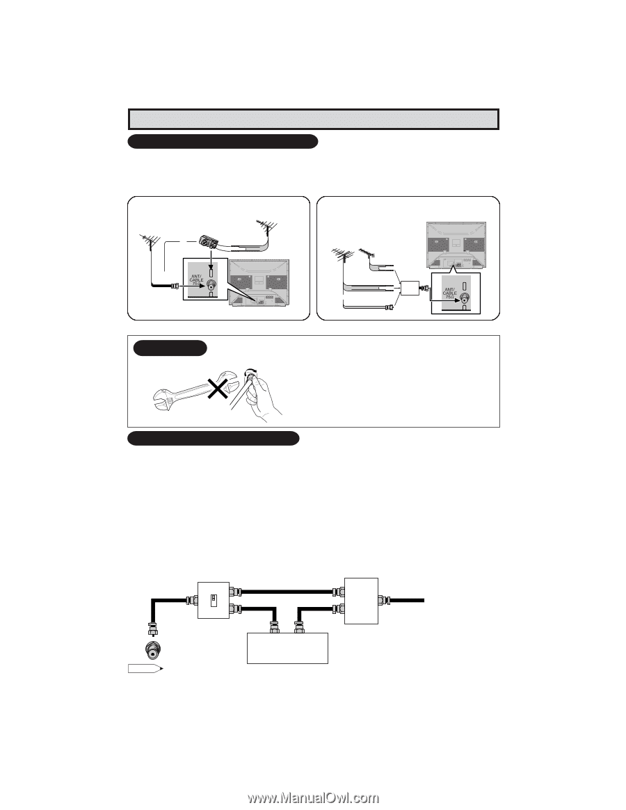
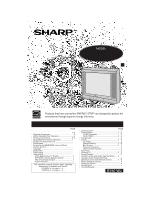
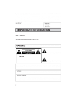
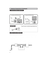
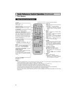
Antenna Connections (Continued) OUTDOOR ANTENNA CONNECTION • Refer to one of the following two diagrams when connecting to an outdoor antenna. A: Using a VHF/UHF combination outdoor antenna. B: Using separate VHF and/or UHF outdoor antenna. • Connect an outdoor antenna cable lead-in to the ANT/CABLE terminal on the rear of the TV set. A. Combination VHF/UHF Antennas VHF/UHF ANTENNA or VHF/UHF ANTENNA 300/75-ohm ADAPTOR (Not supplied) 300-ohm twin-lead 75-ohm coaxial cable REAR OF TV B. Separate VHF/UHF Antenna REAR PANEL VHF UHF ANTENNA ANTENNA 300-ohm twin-lead COMBINER 300-ohm (not supplied) twin-lead IN OUT or 75-ohm coaxial cable NOTICE F-type connector 75-ohm coaxial cable F-type connector should be finger-tightened only. When connecting the RF cable to the TV set, do not tighten F-type connector with tools. If tools are used, it may cause damage to your TV set. (The breaking of internal circuit, etc.) CABLE TV (CATV) CONNECTION • A 75 ohm coaxial cable connector is built into the set for easy hookup. When connecting the 75 ohm coaxial cable to the set, screw the 75 ohm cable to the COAXIAL CABLE CONNECTOR. • Some cable TV companies offer "premium pay channels". Since the signals of these premium pay channels are scrambled, a cable TV converter/descrambler is generally provided to the subscriber by the cable TV company. This converter/descrambler is necessary for normal viewing of the scrambled channels. (Set your TV on channel 3 or 4. Typically one of these channels is used. If this is unknown, consult your cable TV company.) For more specific instructions on installing cable TV, consult your cable TV company. One possible method of utilizing the converter/descrambler provided by your cable TV company is explained below. Please note: RF switch equipped with position A/B (not provided) is required. "A" position on the RF switch (not supplied) : You can view all unscrambled channels using the TV's channel keys. "B" position on the RF switch (not supplied) : You can view the scrambled channels via the converter/ RF switch (not supplied) descrambler using the converter's channel keys. Two-set A signal OUT IN splitter Cable TV Line B OUT (not IN supplied) Cable TV converter/ descrambler (not supplied) Note: • Consult your SHARP Dealer or Service Center for the type of splitter, RF switch or combiner that might be required. 6 32C540 6
-
 1
1 -
 2
2 -
 3
3 -
 4
4 -
 5
5 -
 6
6 -
 7
7 -
 8
8 -
 9
9 -
 10
10 -
 11
11 -
 12
12 -
13
-
14
-
15
-
16
-
17
-
18
-
19
-
20
-
21
-
22
-
23
-
24
-
25
-
26
-
27
-
28
-
29
-
30
-
31
-
32
-
33
-
34
-
35
-
36
-
37
-
38
-
39
-
40
-
41
-
42
-
43
-
44
-
45
-
46
-
47
 |
 |