Sharp LC-20SH7U LC-20SH7U Operation Manual - Page 10
Control Panel, Rear Panel - remote
 |
UPC - 074000363809
View all Sharp LC-20SH7U manuals
Add to My Manuals
Save this manual to your list of manuals |
Page 10 highlights
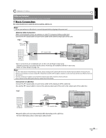
INTRODUCTION 5 Control Panel MENU VOL top of the unit CH INPUT POWER 1 1. MENU button (p13) 2 Press to display the main menu. 3 4 2. VOL - / + buttons (p15) 5 Press to adjust the volume. 3. CH / buttons (p15) Press to select channels or move up/down through the main menu items. 4. INPUT button (p16) • Press to access connected an external device like a DVD player or VCR. • Press to switch between the digital mode (DTV) and analog mode. 5. POWER button (p12) Press to turn the unit on and off. 6. Power Indicator Lights up when power is on. 7. Infrared Sensor Window Receives infrared commands transmitted from the remote control. 5 Rear Panel POWER 6 7 INPUT 2 COMPONENT Y PB PR INPUT 1 COAXIAL S-VIDEO VIDEO AUDIO L R AUDIO L R rear of this unit INPUT 2 COMPONENT Y PB PR INPUT 1 COAXIAL S-VIDEO VIDEO AUDIO L R AUDIO L R 1 2 side of the unit 3 1. ANT jack (p9) RF coaxial cable connection for your antenna or cable box. 2. HEADPHONE jack Headphone connection for personal listening. 3. COMPONENT and AUDIO input jacks (p10) Component video cable connection for an external device. Use component video and audio output jacks of an external device. 4. AUDIO input jacks (p10) RCA audio cable connection for an external device. 5. VIDEO input jack (p11) RCA video cable connection for an external device. 6. S-VIDEO input jack (p10) S-video cable connection for an external device. 7. COAXIAL (digital audio) output jack (p11) Digital audio coaxial cable connection for a decoder or an audio receiver. Use digital audio input jack of an external device. 8. AC power cord Connect to a standard AC outlet to supply power to this unit. 4 5 6 7 8 8 EN
-
 1
1 -
2
-
3
-
4
-
 5
5 -
 6
6 -
 7
7 -
 8
8 -
 9
9 -
 10
10 -
 11
11 -
 12
12 -
 13
13 -
 14
14 -
 15
15 -
16
-
17
-
18
-
19
-
20
-
21
-
22
-
23
-
24
-
25
-
26
-
27
-
28
-
29
-
30
-
31
-
32
-
33
-
34
-
35
-
36
 |
 |
