Singer One Instruction Manual 9 - Page 21
D -- PROJECTION -- the part that projects - name
 |
View all Singer One manuals
Add to My Manuals
Save this manual to your list of manuals |
Page 21 highlights
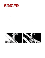
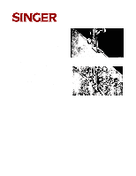
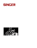
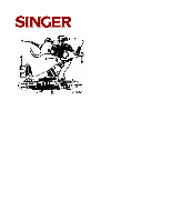
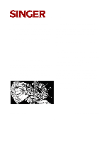
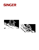
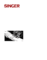
127-3 & 128-3 The names and uses of the principal parts of the ruffler are as fol- lows: (SEE: REFERENCES IN Fig. 26) A -- FOOT -- the part by which the ruffler is attached to the presser bar. B -- FORK ARM-- the section that must be placed astride the needle clamp. C -- ADJUSTING SCREW -- the screw that regulates the fullness of the gather. FIG. 26. THE RUFFLER AND ITS PARTS Ruffler Lines 1, 2, 3, 4 and .5 shown in Fig. 26 indicate where the material is to be placed for various operations, as follows: Line 1 -- the correct position for the material to which the ruffled material is applied. Line 2 -- material to be ruffled. Line 3 -- the facing for the ruffle. Line 4 -- the strip of piping material. Line 5--the edge to be piped. D -- PROJECTION -- the part that projects through tile the slots in the adjusting lever E-- ADJUSTING LEVER -- the lever that sets the ruffler for gathering or for making a plait once at every six stitches or once at every twelve stitches, as desired: also for disengaging the ruffler, when either plaiting or gathering is not desired. F -- ADJUSTING FINGER -- the part which regulates the width or size of the plaits. continued on next page... Refer to Fig. 26 when inserting the material in the ruffler. Table of Contents Previous Page | Next Page 21
-
 1
1 -
2
-
3
-
4
-
5
-
6
-
7
-
8
-
9
-
10
-
11
-
12
-
13
-
14
-
15
-
 16
16 -
 17
17 -
 18
18 -
 19
19 -
 20
20 -
 21
21 -
 22
22 -
 23
23 -
 24
24 -
 25
25 -
 26
26
 |
 |
