Sony CCD TRV16 Service Manual
Sony CCD TRV16 - Hi8 Handycam Camcorder Manual
 |
UPC - 027242551497
View all Sony CCD TRV16 manuals
Add to My Manuals
Save this manual to your list of manuals |
Sony CCD TRV16 manual content summary:
- Sony CCD TRV16 | Service Manual - Page 1
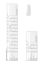
Kong Model CCD-TRV16/TRV46 Taiwan Model CCD-TRV16 Brazilian Model CCD-TR315/TR416 CCD-TRV16 B MECHANISM Photo : CCD-TRV46 NTSC SPECIFICATIONS For MECHANISM ADJUSTMENTS, refer to the "8mm Video MECHANICAL ADJUSTMENT MANUAL VII" (9-973-801-11). Video camera recorder System Video recording system - Sony CCD TRV16 | Service Manual - Page 2
(TRV series only) Dynamic speaker General Power requirements 7.2 V (battery pack) 8.4 V (AC power adaptor) Averege power consumption(when using the battery pack) During camera recording CCD-TR416/TR416PK/TR516/ TR516PK : 2.4 W CCD-TR315/TR716 : 2.5 W During camera recording using LCD CCD-TRV16 - Sony CCD TRV16 | Service Manual - Page 3
¬ G 330X ¬ 510 G G G TYPE C Color ¬ ¬ G 330X ¬ 510 G G G CCDTR716 CCDTRV16 CCDTRV16PK US,CND TYPE D Color ¬ ¬ G 330X ¬ 510P ¬ G G US,CND,E, E HK,BR,TW TRV series only Model Destination Classification View finder Remote commander (RMT-708) Hi8 Standard 8 Lens (Digital ZOOM) Video light CCD - Sony CCD TRV16 | Service Manual - Page 4
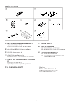
is already installed in your camcorder. 5 Size AA (R6) battery for Remote Commander (2) CCD-TR516/TR516PK/TR716 CCD-TRV36/TRV36PK/TRV43/TRV46/TRV46PK 6 A / V connecting cable (1) 7 Shoulder strap (1) 8 Video P6-15P HB tape CCD-TR416: US/TR516: US/TR716:US CCD-TRV16:US/TRV36:US/TRV43:US/TRV46 - Sony CCD TRV16 | Service Manual - Page 5
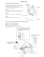
seconds after power is supplied (8.4V) to the battery terminal using the service power cord (J-6082-223-A), the power is shut battery switch of the battery terminal using adhesive tape, etc. Battery terminal ' Method 3. Use the DC IN terminal. (Use the AC power adaptor.) DC IN terminal Battery - Sony CCD TRV16 | Service Manual - Page 6
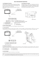
to do. This function consists of two display; selfdiagnosis display and service mode display. Details of the self-diagnosis functions are provided in the Instruc- tion manual. Viewfinder Display window 2. Self-diagnosis display When problems occur while the unit is operating, the counter of the - Sony CCD TRV16 | Service Manual - Page 7
0 0 Video head is dirty. Clean with the optional cleaning cassette. C 2 3 0 0 Non-standard battery is used. Use the InfoLITHIUM battery. LOAD direction 24 4 Phase fault during normal drum operations Remove the battery or power cable, connect, and perform operations from the beginning. Inspect - Sony CCD TRV16 | Service Manual - Page 8
Code Table 7 1. GENERAL This section is extacked from instruction manual of CCD-TRV36/TRV43/TRV46. Using this manual 1-1 Checking supplied accessories 1-1 Installing and Charging the battery pack 1-1 Inserting a cassette 1-2 Camera recording 1-2 Hints for better Shooting 1-4 Checking the - Sony CCD TRV16 | Service Manual - Page 9
DIAGRAMS 4-1. Frame Schematic Diagram (1 4-1 • Frame Schematic Diagram (2 4-4 4-2. Printed Wiring Boards and Schematic Diagrams 4-7 • CD-210/211 (CCD Imager) Board 4-8 • VC-215 (Camera, Y/C Processor, IN/OUT, REC/PB Head Amp, Servo/System Control, Servo, Audio, IR Transmitter, Mode Control - Sony CCD TRV16 | Service Manual - Page 10
/ TRV36PK/TRV43/TRV46/TRV46PK 5-51 8. Standerd8 REC Y Current Adjustment (VC-215 board) (CCD-TR315/TR416/TR416PK CCD-TRV16/TRV16PK 5-52 9. Hi8 REC L Level Adjustment (VC-215 board) (CCD-TR516/TR516PK/TR716 CCD-TRV36/ TRV36PK/TRV43/TRV46/TRV46PK 5-53 10. Standerd8 REC L Level Adjustment (VC-215 - Sony CCD TRV16 | Service Manual - Page 11
CCD-TR315/TR416/TR416PK/TR516/TR516PK/TR716 CCD-TRV16/TRV16PK/TRV36/TRV36PK/TRV43/TRV46/TRV46PK SECTION 1 GENERAL This section is extracted from instruction manual of CCD-TRV36/TRV43/TRV46. - Sony CCD TRV16 | Service Manual - Page 12
- Sony CCD TRV16 | Service Manual - Page 13
- Sony CCD TRV16 | Service Manual - Page 14
- Sony CCD TRV16 | Service Manual - Page 15
- Sony CCD TRV16 | Service Manual - Page 16
- Sony CCD TRV16 | Service Manual - Page 17
- Sony CCD TRV16 | Service Manual - Page 18
- Sony CCD TRV16 | Service Manual - Page 19
- Sony CCD TRV16 | Service Manual - Page 20
- Sony CCD TRV16 | Service Manual - Page 21
- Sony CCD TRV16 | Service Manual - Page 22
- Sony CCD TRV16 | Service Manual - Page 23
- Sony CCD TRV16 | Service Manual - Page 24
- Sony CCD TRV16 | Service Manual - Page 25
- Sony CCD TRV16 | Service Manual - Page 26
- Sony CCD TRV16 | Service Manual - Page 27
- Sony CCD TRV16 | Service Manual - Page 28
- Sony CCD TRV16 | Service Manual - Page 29
- Sony CCD TRV16 | Service Manual - Page 30
- Sony CCD TRV16 | Service Manual - Page 31
-TR315/TR416/TR416PK/TR516/TR516PK/TR716 CCD-TRV16/TRV16PK/TRV36/TRV36PK/TRV43/TRV46/TRV46PK SECTION 2 DISASSEMBLY The equipment can be removed using the following procedure. VIDEO CAMERA RECORDER 2-1. FRONT PANEL BLOCK VIDEO LIGHT BLOCK (Video light models only) 2-4. CABINET (R) BLOCK 2-2. LB-54 - Sony CCD TRV16 | Service Manual - Page 32
54, VF-119 AND VF-120 BOARDS (Color view finder model CCD-TR416/TR416PK/TR516/TR516PK/TR716) 1 Tilt-up the EVF block 54 board 8 VF-120 board 2-3. REMOVAL OF VF-99 AND CRT ASSEMBLY (B/W view finder model CCD-TR315 and TRV series) 1 Tilt-up the EVF block to the direction of arrow A. 3 Remove the EVF - Sony CCD TRV16 | Service Manual - Page 33
Lens assembly is put into the hole of the IR knob when attaching. (TR series) (TRV series) 3Three screws (M2 x 4) 5Flat cable (FFC-257F) CN911, 45P 2Two screws (M2 x 4) Pin 3Three screws (M2 x 4) 5Flat cable (FFC-257F) CN911, 45P 2Two screws (M2 x 4) Pin 4Cabinet (R) block IR knob 1Two screws - Sony CCD TRV16 | Service Manual - Page 34
OF ZOOM LENS BLOCK AND VL-21/22 BOARD -Video light models- CCD-TR516/TR516PK/TR716 CCD-TRV36/TRV36PK/TRV43/TRV46/TRV46PK -No video light models- CCD-TR315/TR416/TR416PK CCD-TRV16/TRV16PK 7Two screws (M2 x 3) 8Shoe bracket No video light models 3Screw (M2 x 3) 5FP-623 flexible board CN501 - Sony CCD TRV16 | Service Manual - Page 35
, 16P from video head 3 Flexible CCD-TR315 and TRV series 2VF flexible retainer sheet 4Tapping screw 3Tapping screw 2VF flexible retainer sheet 4Tapping screw 5VF base assembly 7Three tapping screws 1FP-57 flexible board CN007, 20P 6Tilt-up the EVF block to the direction of arrow. 1Flat cable - Sony CCD TRV16 | Service Manual - Page 36
tapping screws 3Control switch block (MF-8500) 2-14. REMOVAL OF IR COVER, CF-61 BOARD AND LCD PANEL...(TRV series) 4Flat cable (FFC-235) CN008, 4P Phase adjustment S024 5Flat cable (FFC-257S) CN001, 45P 0CF-61 board 9Five tapping screws !™Two tapping screws CN008 6Harness !¶LCD panel !§Four - Sony CCD TRV16 | Service Manual - Page 37
and connect as shown in the figure after each parts has been removed. -TR series- Extension cord 70P (J-6082-439-A) DD-117 board : CN931 - VC-215 board : CN915 Control switch block (FK-8500) Battry panel block DD-117 board Cabinet (L) block -TRV series- Extension cord 70P (J-6082-439-A) DD-117 - Sony CCD TRV16 | Service Manual - Page 38
)...B/W EVF models only FP-58...Video light models only FP-680 FP-355 FP-356 Flat cable (FFC-257F) FP-621 Function key (FK-8500) FP-249 FP-56 FP-248 FP-221 Capstan motor Video head Drum motor FP-642...TRV series only Manual forcus (MF-8500) FP-620...TR716 & TRV series only FP-220 - Sony CCD TRV16 | Service Manual - Page 39
- Sony CCD TRV16 | Service Manual - Page 40
IC202 66 3.1Vp-p CAMERA REC H IC202 6 0.84Vp-p CAMERA REC H IC202 3 0.34Vp-p CAMERA REC H IC202 33 0.9Vp-p CAMERA REC H IC201 20 CAMERA REC V IC201 19 3Vp-p 3Vp-p CAMERA REC H IC202 26 0.18Vp-p CAMERA REC H IC202 23 0.18Vp-p CAMERA REC 7.16 MHz IC201 8 3.2Vp-p CAMERA REC V IC202 81 - Sony CCD TRV16 | Service Manual - Page 41
3.1V 3.1V 20 MHz IC402 1 1.7Vp-p 3.1V 4V IC402 48 3Vp-p 3.1V 13usec IC402 70 3Vp-p 2V IC402 47 3Vp-p 3.1V TR M TRV COLO STEA - Sony CCD TRV16 | Service Manual - Page 42
3Vp-p 116 13usec IC402 69 3Vp-p 1.2msec IC402 115 3Vp-p 13usec IC402 68 3Vp-p 506 kHz IC801 64 0.76Vp-p 507 kHz IC801 4 0.76Vp-p 3.1V - Sony CCD TRV16 | Service Manual - Page 43
TR MODEL : CCD-TR315/TR416/TR416PK/TR516/TR516PK/TR TRV MODEL : CCD-TRV16/TRV16PK/TRV36/TRV36PK/TRV43/ REMOTE COMMANDER MODEL : CCD-TR516/TR516PK/TR71 CCD-TRV36/TRV36PK/TRV4 VIDEO LIGHT MODEL : CCD-TR516/TR516PK/TR716 CCD-TRV36/TRV36PK/TRV43/TRV46/T (VIDEO LIGHT M (VIDEO LIGHT MODEL) (TRV MODEL T - Sony CCD TRV16 | Service Manual - Page 44
3.58 MHz IC751 7 0.25Vp-p 2usec IC751 15 0.5Vp-p 0.09usec IC751 16 0.34Vp-p 3.1V TR716 only TR MODEL : CCDTRV MODEL : CC IR TRANSMITTER - Sony CCD TRV16 | Service Manual - Page 45
IC5502 16 H 4.7Vp-p H IC5502 13 0.7Vp-p 2H IC5502 20 4.2Vp-p H IC5502 8 0.44Vp-p H IC5502 9 0.2Vp-p H IC5502 10 0.2Vp-p FRPT FRPV 3.1V IC5601 26 Approx.5.8MHz : 4.1Vp-p IC5602 DAC - Sony CCD TRV16 | Service Manual - Page 46
3Vp-p 3.4Vp-p 1.84 MHz IC5404 23 , 24 3Vp-p 7.852 kHz IC5404 20 , 21 2.7Vp-p 11.06 MHz IC5404 41 V IC5404 18 3Vp-p COLOR EVF MODEL : CCD-TR - Sony CCD TRV16 | Service Manual - Page 47
T901/T902 - Sony CCD TRV16 | Service Manual - Page 48
20 20 3.1V 3.1V 3.1V 3.1V 3.1V 3.1V 3.1V 3.1V 3.1V 3.1V 3.1V - Sony CCD TRV16 | Service Manual - Page 49
(TR MODEL) (COLOR EVF MODEL) (B/W EVF MODEL) - Sony CCD TRV16 | Service Manual - Page 50
- Sony CCD TRV16 | Service Manual - Page 51
Printed Wiring Boards. There are few cases that the part isn't mounted in this model is printed on this diagram. • Chip transistor C Q BE VF-99...B/W EVF models only (B/W EVF) CD-210...TR series only CD-211...TRV series only (CCD imager) PD-107...TRV series only RGB decoder, LCD, LCD drive, Back - Sony CCD TRV16 | Service Manual - Page 52
5 E-4 R479 A-2 R651 F-2 6 E-4 R480 A-2 R652 F-3 7 D-4 R481 A-2 R653 F-3 4 B-9 R482 A-2 R654 F-3 5 C-9 R483 A-1 R655 F-2 6 B-9 R484 A-1 R662 E-3 G 7 C-9 R485 A-1 R663 F-3 2 C-9 R486 B-1 R664 F-2 4 B-9 R487 A-1 R665 F-3 6 C-9 R504 E-6 R678 - Sony CCD TRV16 | Service Manual - Page 53
D-13 D-13 D-14 D-14 D-14 D-13 D-13 D-13 E-13 E-13 G-12 G-13 G-15 F-14 G-14 G-14 F-15 G-14 G-13 G-14 G-14 G-16 E-16 E-16 E-17 E-17 E-17 E-17 E-17 E-17 E-17 E-17 E-16 F-16 G-16 F-16 F-11 F-11 F-12 F-12 F-12 F-12 F-11 E-12 E-12 E-12 E-12 F-12 F-12 A-15 B-11 A-13 F-13 D551 D610 FB001 FB002 - Sony CCD TRV16 | Service Manual - Page 54
MERA REC 2.3Vp-p NTSC : 28.636 MHz 01 5 MERA REC 2.3Vp-p NTSC : 14.32 MHz 01 11 , 12 MERA REC 7Vp-p H IC501 25 , 26 MERA REC 7Vp-p H IC501 28 , 31 MERA REC H IC501 44 3Vp-p MERA REC V IC501 45 3Vp-p MERA REC 3.2Vp-p sec IC502 2 - 10 MERA REC H IC502 26 1.3Vp-p PB 0.4Vp-p - Sony CCD TRV16 | Service Manual - Page 55
- Sony CCD TRV16 | Service Manual - Page 56
- Sony CCD TRV16 | Service Manual - Page 57
REC PB - Sony CCD TRV16 | Service Manual - Page 58
- Sony CCD TRV16 | Service Manual - Page 59
- Sony CCD TRV16 | Service Manual - Page 60
52 51 - Sony CCD TRV16 | Service Manual - Page 61
56 55 54 53 - Sony CCD TRV16 | Service Manual - Page 62
TR series only (Control) VL-21... TR516/TR516PK/TR716 VL-22... TRV36/TRV36PK/TRV43/ TRV46/TRV46PK (Video light) PJ-90...TR series PJ-91...TRV series (AV Out) PB 57 3.58 MHz IC751 7 58 2usec IC751 15 59 0.09usec IC751 16 60 0.09usec IC751 22 61 H IC751 41 0.25Vp-p 0.5Vp-p 0.34Vp-p 0.7Vp-p 0.5Vp-p - Sony CCD TRV16 | Service Manual - Page 63
62 63 - Sony CCD TRV16 | Service Manual - Page 64
SE-80/81 BOARD (SIDE A) C451 C-7 C452 D-3 C453 B-7 C454 E-6 C455 C-3 C456 C-3 C457 C-2 C458 C-3 C459 C-7 C460 E-6 C461 C-6 C462 C-6 C463 C-3 C464 C-6 C465 C-3 C466 C-6 C467 A-2 C468 A-6 C469 A-2 C470 A-6 C471 B-3 CN451 A-3 D451 A-6 D452 A-6 IC451 C-6 - Sony CCD TRV16 | Service Manual - Page 65
S VIDEO PJ-90/91 BOARD C101 D-4 C102 D-3 C103 C-3 C104 C-3 C105 D-1 C106 D-2 C107 C-1 C108 D-1 C109 D-5 C110 C-5 C111 C-1 CN101 D-2 D101 D-1 D102 C-3 D103 C-3 D104 C-5 D105 C-5 D106 D-5 J101 B-3 L101 D-3 L102 C-3 - Sony CCD TRV16 | Service Manual - Page 66
/346 BOARD (SIDE B) E VTR D POWER CAMERA C B A 09 1 2 3 • For Printed Wiring Boards. There are few cases that the part isn't mounted in this model is printed on 22... TRV36/TRV36PK/TRV43/ TRV46/TRV46PK (Video light) PJ-90...TR series PJ-91...TRV series (AV Out) M L O MIC (PLUG IN POWER) 4 - Sony CCD TRV16 | Service Manual - Page 67
- Sony CCD TRV16 | Service Manual - Page 68
OR PUSH 5SEC 5 6 odels only lor EVF models only ) R series only VL-21... TR516/TR516PK/TR716 VL-22... TRV36/TRV36PK/TRV43/ TRV46/TRV46PK (Video light) PJ-90...TR series PJ-91...TRV series (AV Out) TITLE PICTURE EFECT CF-60 BOARD (SIDE A) EXPOSUE AE-DIAL 7 8 MENU SELECT-DIAL 9 10 11 12 - Sony CCD TRV16 | Service Manual - Page 69
NO MARK : CAMERA REC MODE 2.9 0.1 1.4 1.4 1.4 1.4 1.6 1.4 1.4 1.9 1.4 1.4 3 1.4 3 1.4 3 1.4 2.9 1.4 2.9 1.4 1.4 1.4 1.4 1.4 1.4 1.4 1.4 - Sony CCD TRV16 | Service Manual - Page 70
- Sony CCD TRV16 | Service Manual - Page 71
CF-61 BOARD (SIDE A) DATE TIME COUNTER RESET REC MODE 5SEC PUSH NOR DISPLAY TITLE END SEARCH MENU (LITHIUM BATTERY HOLDER) PICTURE EFECT SELECT-DIA 1-672-46 7 8 9 10 11 12 13 14 - Sony CCD TRV16 | Service Manual - Page 72
BRIGHT (-) C 8 765 4 3 2 1 B VOLUME (+) A VOLUME (-) 09 1 2 VF-99...B/W EVF models only (B/W EVF) CD-210...TR series only CD-211...TRV series only (CCD imager) PD-107...TRV series only RGB decoder, LCD, LCD drive, Back light 15 3 4 • For Printed Wiring Boards. • This board is four-layer - Sony CCD TRV16 | Service Manual - Page 73
CAMERA REC 1 H IC5502 8 2 H IC5502 9 3 H IC5502 10 4 H IC5502 13 5 H IC5502 16 6 2H IC5502 20 7 2H IC5502 22 8 2H IC5502 24 - Sony CCD TRV16 | Service Manual - Page 74
- Sony CCD TRV16 | Service Manual - Page 75
- Sony CCD TRV16 | Service Manual - Page 76
B-3 R932 B-3 RV903 A-3 RV904 A-3 T901 B-3 T902 B-3 TH901 C-3 W901 B-3 odels only .TR series only .TRV series only ger) PD-107...TRV series only RGB decoder, LCD, LCD drive, Back light VF-99 BOARD CAMERA REC 1 H IC901 11 1Vp-p (TYPE 2) (TYPE 3) BOARD TYPE TYPE 2 TYPE 3 Ref. No. C910 - Sony CCD TRV16 | Service Manual - Page 77
3Vp-p 7.2Vp-p 7.5Vp-p 7.6Vp-p 3Vp-p 3Vp-p 3Vp-p 3.4Vp-p 2.7Vp-p - Sony CCD TRV16 | Service Manual - Page 78
- Sony CCD TRV16 | Service Manual - Page 79
3 12 A-4 A-2 A-1 A-3 A-4 A-3 A-3 A-3 A-3 A-3 A-3 B-3 B-3 B-3 A-3 A-3 B-3 B-4 A-4 A-2 A-3 A-3 A-4 A-4 B-4 B 1-668-944- 13 A 09 1 2 3 4 LB-54 BOARD C5351 A-3 C5352 A-3 C5353 A-3 C5354 B-3 C5355 B-3 C5356 A-3 CN5351 A-4 D5351 A-1 L5351 A-3 L5352 A-3 ND5351 B-1 Q5351 B-3 R5351 A-3 T5351 B-4 - Sony CCD TRV16 | Service Manual - Page 80
C804 E-3 L804 E-9 R826 D-3 C805 E-2 L805 B-7 R827 E-3 C806 E-2 L806 C-8 R828 E-3 C807 D-2 L807 C-6 R829 C-2 C808 E-3 L808 B-8 R829 D-2 C809 D-2 L809 C-7 R830 D-2 C810 D-3 L810 B-4 R831 F-3 G C811 D-2 L811 B-3 R832 D-3 C812 D-3 L812 B-3 R833 D-2 - Sony CCD TRV16 | Service Manual - Page 81
7.7 7.9 1.9 7.9 3.1 3.1 7.8 - Sony CCD TRV16 | Service Manual - Page 82
/TR716 CCD-TRV16/TRV16PK/TRV36/TRV36PK/TRV43/TRV46/TRV46PK SECTION 5 ADJUSTMENTS 5-1. CAMERA SECTION ADJUSTMENTS Refer to page 3 as Table for distinction functions of models and classification 1-1. PREPARATIONS BEFORE ADJUSTMENT (CAMERA SECTION) 1-1-1. List of Service Tools • Oscilloscope - Sony CCD TRV16 | Service Manual - Page 83
removing, note down the self-diagnosis data and data on the history use. (Refer to the "Service Mode" of "VIDEO SECTION ADJUSTMENT" for the data on the history use.) Note 4: Setting the "Forced Camera Power ON" Mode 1) Select page: 0, address: 01, and set data: 01. 2) Select page: D, address: 10 - Sony CCD TRV16 | Service Manual - Page 84
Extension cable(16P) (J-6082-357-A) VL-21 board CN151 VIDEO cable(70P) (J-6082-439-A) Battery terminal (Note 1) Regulaterd power supply (8.4 ± 0.1 Vdc) Battery switch CN935 CN934 CN801 CN931 DD-117 board Adjusting remote commander LANC terminal Must be connected when performing the VIDEO - Sony CCD TRV16 | Service Manual - Page 85
CF-61 board CN001 Extension cable(70P) (J-6082-439-A) Battery terminal (Note 2) Regulaterd power supply (8.4 ± 0.1 Vdc) Battery switch CN935 CN934 Adjusting remote commander LANC jack CN801 CN931 CN933 DD-117 board Must be connected when performing the VIDEO system. CPC-7 jig (J-6082-382 - Sony CCD TRV16 | Service Manual - Page 86
display V-OUT/LCD 7. FOCUS switch (MF-8500 MANUAL 8. PROGRAM AE (CF-60/61 board Auto 9. EFECT (CF-60/61 board OFF 11. 16 : 9 WIDE (Menu display OFF 2. Adjusting Video output terminal output wavefom) BA V Enlargement Difference in level Fig. b. (TV monitor picture) A B Adjust the camera - Sony CCD TRV16 | Service Manual - Page 87
of the adjusting remote commander to "HOLD" (SERVICE position). If it has been properly connected, the SEARCH+ button is pressed, and decreases when the EDIT SEARCH- button is pressed. There are altogether 16 pages, from 0 to F. Hexadecimal notation 0123456 789ABCDE F LCD Display 0 1 2 3 4 5 - Sony CCD TRV16 | Service Manual - Page 88
-Decimal notation 2 n The lower digits of the hexadecimal notation 0 1 2 3 4 5 6 7 8 9 A B C D E F The upper digits of the hexadecimal notation (A) (b) (c) (d) (E) (F) 0 0 1 2 3 4 5 6 7 8 9 10 11 12 13 14 15 1 16 17 18 19 20 21 22 23 24 25 26 27 28 29 30 31 2 32 33 34 35 36 37 38 39 40 41 - Sony CCD TRV16 | Service Manual - Page 89
, change the data of the "Fixed data-2" address shown in the following tables by manual input. Modifying Method: 1) Before changing the data, select page: 0, address: 01, Note : If copy the data built in the different model, the camcorder may not operate. 3) When changing the data, press the PAUSE - Sony CCD TRV16 | Service Manual - Page 90
Fixed data-2 14 (Modified data, copy the data 15 built in the same model.) 16 17 18 19 1A 1B 1C 1D 1E 1F 20 21 22 23 24 25 26 2B 00 2C 00 2D 00 2E Fixed data-2 2F 64 Fixed data-1 30 88 Battery end adj. 31 8D 32 A8 33 BD 34 C8 35 05 Fixed data-1 36 02 - Sony CCD TRV16 | Service Manual - Page 91
Hi8 model :CCD-TR516/TR516PK/TR716 CCD-TRV36/TRV36PK/TRV43/TRV46/TRV46PK Standard8 model : CCD-TR315/TR416/TR416PK CCD-TRV16/TRV16PK Address 00 to 0F 10 11 12 13 14 15 16 Note 2 : Hi8 model/ Standard8 model REC C current adj. IR video deviation Adj. IR audio deviation Adj. IR video carrier freq. Adj - Sony CCD TRV16 | Service Manual - Page 92
9C 9D 9E 9F A0 A1 A2 A3 A4 A5 A6 A7 A8 A9 AA AB AC AD AE AF B0 B1 B2 B3 B4 B5 B6 B7 B8 B9 BA BB BC adj. Fixed data-1 Fixed data-2 Fixed data-1 Fixed data-2 Fixed data-1:CCD-TR516/TR516PK, TRV36/TRV36PK Fixed data-2:CCD-TR716, TRV43/TRV46/TRV46PK Fixed data-2 Fixed data-1 Fixed data-2 Fixed data - Sony CCD TRV16 | Service Manual - Page 93
03 04 05 06 07 08 09 0A 0B 0C 0D 0E 0F 10 11 12 13 14 15 16 17 18 19 1A 1B 1C 1D 1E 1F 20 21 22 23 24 25 26 27 28 29 data-2 Fixed data-1 Fixed data-2 Fixed data-1 Fixed data-2 Fixed data-1 TR model:Fixed data-1/TRV model:Fixed data-2 Fixed data-1 Fixed data-2 Fixed data-1 Fixed data-2 Fixed data-1 - Sony CCD TRV16 | Service Manual - Page 94
9E 9F A0 A1 A2 A3 A4 A5 A6 A7 A8 A9 AA AB AC AD AE AF B0 B1 B2 B3 B4 B5 B6 B7 B8 B9 BA data-2 Fixed data-1 Fixed data-2 Fixed data-1 TR model:Fixed data-1/TRV model:Fixed data-2 Fixed data-2 Fixed data-1 Fixed data-2 TR model : Fixed data-1 TRV model : Fixed data-2 VCO adj. (Color EVF) Bright adj. ( - Sony CCD TRV16 | Service Manual - Page 95
SYSTEM ADJUSTMENTS Before perform the camera system adjustments, Check that the specified value of "28MHz Origin Oscillation Adjustment", "Y OUT level Adjustment" and "C OUT level Adjustment" of "VIDEO SYSTEM ADJUSTMENT" are satisfied. 1. G-CAM flip Adjustment Set the color reproduction conditions - Sony CCD TRV16 | Service Manual - Page 96
X1' using the following equations (decimal notation calculation). A'= W2'+ K1'- W1'- K2' Equation 1 B'= W1' - K1' Equation 2 X1'=[1696+(48 x A')-(16 x B')] / A' Equation 3 16)Convert X1' to hexadecimal notation, and obtain X1. (Round off to one decimal place) 17)Select page: F, address: 2F - Sony CCD TRV16 | Service Manual - Page 97
lens flange back adjustment is carried out automatically. In whichever case, the focus will be deviated during auto focusing/manual focusing. 3-1. Flange Back Adjustment(1) Subject Measurement Point Measuring Instrument Adjustment Page Adjustment Address Flange back adjustment chart (2.0 m from - Sony CCD TRV16 | Service Manual - Page 98
Value Color bar chart standard picture frame (1.5m from the front of the lens) Video output terminal Oscilloscope and TV monitor A=B, C=D, t=0 ± 0.1msec Setting method: 1) Adjust the zoom and the camera direction, and set to the specified position. 2) Mark the position of the picture frame - Sony CCD TRV16 | Service Manual - Page 99
is produced. Subject Measurement Point Measuring Instrument Adjustment Page Adjustment Address Specified Value Color bar chart standard picture frame Video output terminal Vectorscope F 34, 36, F5, F6 All color luminance points should settle within each color reproduction frame. Switch - Sony CCD TRV16 | Service Manual - Page 100
to Table 5-1-2. "Hexadecimal notation - decimal notation conversion table" of "Service mode".) 8) Calculate D3' using the following equations. (Equations 1 - 14 Equation 4 15) Convert D6' to hexadecimal notation, and obtain D6. 16) Select page: F, address: 3D, set data: D6, and press the PAUSE - Sony CCD TRV16 | Service Manual - Page 101
9. Auto White Balance Standard Data Input Subject Adjustment Page Adjustment Address Clear chart (Color bar standard picture frame) F 70 to 73 Note 1: Perform "Color Reproduction Adjustment" before this adjustment. Note 2: Check that the data of page: 2, address: 02 is data: 00. If not, turn the - Sony CCD TRV16 | Service Manual - Page 102
Measuring Instrument Specified Value Clear chart (Color bar standard picture frame) Filter C14 for color temperature correction ND filter 1.0 and 0.3 video output terminal Vectorscope Fig. 5-1-11. A to C Switch setting: 1) NIGHT SHOT switch OFF Checking method: 1) Check that the lens is not - Sony CCD TRV16 | Service Manual - Page 103
12. Angular Velocity Sensor Sensitivity Check (CCD-TR716/TRV43/TRV46/TRV46PK) • This adjustment is performed check the operations. • Note down the sensitivity displayed on the angular velocity sensor of the repair parts. At this time, note down also to which board it was attached to. Be sure to - Sony CCD TRV16 | Service Manual - Page 104
CCD-TR416/TR416PK/TR516/TR516PK/TR716) Note 1: The back light (fluorescent tube) is driven by a high voltage AC No. Signal Name 1 LANC SIG 2 XCPC IN 3 IR VIDEO 4 AFC F0 5 BPF MONI 6 PB RF 7 RF AGC 13 EVF BL 14 EVF BL 4.75V 15 VCO 16 EVF VG 1. EVF Initial Data Input Mode Signal - Sony CCD TRV16 | Service Manual - Page 105
of the adjusting remote commander. 6) Select page: 0, address: 01, and set data: 00. H 3. Bright Adjustment (VF-119 board) Set the level of the VIDEO signal for driving the LCD to the specified value. If deviated, the screen image will be blackish or saturated (whitish). Mode Signal Measurement - Sony CCD TRV16 | Service Manual - Page 106
4. Contrast Adjustment (VF-119 board) Set the level of the VIDEO signal for driving the LCD to the specified value. If deviated, the screen image will be blackish or saturated (whitish). Mode Signal Measurement Point Measuring - Sony CCD TRV16 | Service Manual - Page 107
1-5. MONOCHROME ELECTRONIC VIEWFINDER SYSTEM ADJUSTMENTS Note: CCD-TR315 CCD-TRV16/TRV16PK/TRV36/TRV36PK/TRV43/ TRV46/TRV46PK 1-5-1. horizontal direction, and adjust with the center section of the modifying position. Fig. 5-1-16. Fig. 5-1-17. VF-99 BOARD (SIDE A) SOL901 C909 Fig. 5-1-18 - Sony CCD TRV16 | Service Manual - Page 108
1-5-4. Aberration Adjustment Mode Signal Specified Value VTR stop Dot pattern b1 2 • a1 b2 0.8 • a2 Adjusting method: 1) Adjust the aberration adjustment ring so that the tracing of the dot satisfies the specified value. 2) If the centering becomes displaced here, perform the centering adjustment - Sony CCD TRV16 | Service Manual - Page 109
1-5-6. Vertical Amplitude Adjustment (VF-99 board) Mode Signal Adjusting Element Specified Value Playback Alighment tape : For checking operations (WR5-5NSP) Monoscope section RV903 10 ± 3% Adjusting method: 1) Adjust RV903 so that the vertical direction over scan becomes 10 ± 3% (Top and bottom - Sony CCD TRV16 | Service Manual - Page 110
1-6. LCD SYSTEM ADJUSTMENT (TRV series) Note1: The back light (fluorescent tube) is driven by a high volt- age AC power supply. Therefore, LCD model: PD-107board, Ref. No.5000 series Note5: LCD model : CCD-TRV16/TRV16PK/TRV36/TRV36PK/TRV43/ TRV46/TRV46PK [Adjusting connector] Most of the measuring - Sony CCD TRV16 | Service Manual - Page 111
2. VCO Adjustment (PD-107 board) Set the VCO freerun frequency. If deviated, the LCD screen will be blurred. Mode VTR stop Signal Measurement point No signal Pin 2 of CN5501 (VCO VOLTAGE) of PD-107 board Measuring instrument Oscilloscope Adjustment page E Adjustment address D6 Specified - Sony CCD TRV16 | Service Manual - Page 112
set data: 00. 8) Select page: 0, address: 01, and set data: 00. White Pedestal 5. Contrast Adjustment (PD-107 board) Set the level of the VIDEO signal for driving the LCD to the specified value. If deviated, the screen image will be blackish or saturated (whitish). Mode Signal Measurement point - Sony CCD TRV16 | Service Manual - Page 113
6. V-COM Adjustment (PD-107 board) Set the common electrode drive signal level of LCD to the specified value. Mode Signal Measurement point Measuring instrument Adjustment page Adjustment address Specified value VTR stop No signal Pin 4 of CN5501 (PANEL COM) of PD-107 board Oscilloscope E D5 A = - Sony CCD TRV16 | Service Manual - Page 114
Check on LCD display E D1, D2 The LCD screen should not be colored. Note1: Check the white balance only when replacing the following parts. If necessary, adjust them. 1. LCD panel 2. Light induction plate 3. IC5502 Adjusting method: 1) Select page: 0, address: 01, and set data: 01. 2) Select page - Sony CCD TRV16 | Service Manual - Page 115
camera power supply ON mode are to be used the tape path face (tape guide, drum, capstan shaft, pinch mm Video Mechanical Adjustment Manual VIDEO 4 AFC F0 5 BPF MONI 6 PB RF 7 RF AGC IN 8 REG GND Pin No. Signal Name 9 RF AGC OUT 10 REC RF 11 RF SWP 12 CAP FG 13 EVF BL 14 EVF BL 4.75V 15 VCO 16 - Sony CCD TRV16 | Service Manual - Page 116
to the LANC jack, and set the HOLD switch to the "ADJ" side, or press the battery switch of the battery terminal using adhesive tape, etc. 14) Power code Part Code: J-6082-223-A 15) AFM DEV jig (J-6082-312-A) 16) IR Receiving jig (J-6082-383-A) 17) Extension cable (48P, 0.8mm) (J-6082-188-A) - Sony CCD TRV16 | Service Manual - Page 117
battery end adjustment. To remove, disconnect the following connectors. 1. VC-215 board CN501 (16P, 0.5mm) 2. VC-215 board CN551 (23P, 0.5mm) 4) The video light model need not be assembled.If removing it. disconnect the following connect. 1. VC-215 board CN909 (4P 0.8mm) 5) Cabinet (R) ( Camera - Sony CCD TRV16 | Service Manual - Page 118
Battery terminal Regulated power supply 8.4±0.1Vdc Main Unit VIDEO VIDEO terminal Fig. 5-3-2. TV monitor Connect when using the camera MP Tape speed Usage Tape path SP adjustment Switching position adjustment Hi8 ME SP Frequency characteristics adjustment Standard8 MP SP Operation check ( - Sony CCD TRV16 | Service Manual - Page 119
Fig. 5-3-3. shows the 75% color bar signals recorded on the alignment tape. Note: Measure using the VIDEO terminal (Terminated at 75 Ω). Fig. 5-3-3. Color Bar Signals of the Alignment Tape - Sony CCD TRV16 | Service Manual - Page 120
Hi8 Standard 8 3-1-8. Service Mode Additional note on adjustment Note: After the completion of the all adjustments, cancell the ser- vice mode by either of the following ways. 1) Unplug the main power supply and remove the lithium battery Normal Camera power ON VTR power ON Camera+VTR power - Sony CCD TRV16 | Service Manual - Page 121
1st emergency occurs 13 Lower: Target MSW code of the 1st emergency occurs 14 2nd EMG code Upper: MSW code when the mechanism starts shifting 16 the 2nd time Lower: MSW code when the 2nd emergency occurs 17 Lower: Target MSW code of the 2nd emergency occurs 18 Last EMG code - Sony CCD TRV16 | Service Manual - Page 122
(mode switch, mechanism position) when errors occurs. • The upper parts of the data of addresses 12, 16 and 1A represent, when the mechanism position is to be moved, the MSW codes at the start of movement (when moving the loading motor). • The lower parts of the data of addresses 13, 17 and 1B - Sony CCD TRV16 | Service Manual - Page 123
3. Bit value discrimination Bit values must be discriminated using the display data of the adjusting remote commander for the following items. Use the table below to discriminate if the bit value is "1" or "0". An Bn Remote controller display 0 1 2 3 4 5 6 7 8 9 A (A) B (b) C (c) D (d) E (E) F (F) - Sony CCD TRV16 | Service Manual - Page 124
61 S012) (CF-60/61 S017) (MF-8500 S002) INFINITY (MF-8500 S001) MANUAL (MF-8500 S001) (MF-8500 S001) 65 DATE COUNTER END SEARCH TITLE DISPLAY (AD5: MIC jack 5 AUDIO terminal 6 VIDEO terminal When bit value=1 When bit value=0 MIC jack is used Monaural VIDEO terminal is used Using method: 1) - Sony CCD TRV16 | Service Manual - Page 125
Using method: 1) The record of use data is displayed at page 3, addresses: A2 to AA. Note: This data will be erased when the coin lithium battery is removed (reset). - Sony CCD TRV16 | Service Manual - Page 126
battery will shorten. The image at the battery end will also be rough. Mode Subject Measurement Point Measuring Instrument Adjustment Page Adjustment Address Camera VIDEO LIGHT OFF (VIDEO LIGHT model) Connection: 1) Connect the regulated power supply and the digital voltmeter to the battery - Sony CCD TRV16 | Service Manual - Page 127
If it is not correct. jitters will increase. Mode Subject Measurement Point Measuring Instrument Adjustment Page Adjustment Address Specified value Camera recording (SP mode) Arbitrary Pin !™ of CN910 (CAP FG) Oscilloscope F 69 Duty = 50±0.5% Adjusting method: 1) Select page: 0, address: 01, and - Sony CCD TRV16 | Service Manual - Page 128
SYSTEM ADJUSTMENTS Video system adjustments must be performed in the following order. [Adjusting Order] 1. 28MHz origin oscillation adjustment 2. AFC f0 adjustment 3. Filter f0 adjustment 4. Y OUT level adjustment 5. C OUT level adjustment 6. RP filter f0 adjustment 7. Hi8 REC Y current adjustment - Sony CCD TRV16 | Service Manual - Page 129
0, address: 01, and set data: 00. 3. Filter f0 Adjustment (VC-215 board) Minimize the chroma signal residual components during composite video signal input. Mode Signal Measurement Point Measuring Instrument Adjustment Page Adjustment Address Specified Value VTR stop No signal Pin 3 of CN910 (IR - Sony CCD TRV16 | Service Manual - Page 130
Address Specified Value VTR stop No signal VIDEO terminal (75Ω terminated ) Oscilloscope F 49 A = 286±5mV Note 1 : Hi8 model CCD-TR516/TR516PK/TR716 CCD-TRV36/TRV36PK/TRV43/TRV46/TRV46PK : Standard8 model CCD-TR315/TR416/TR416PK CCD-TRV16/TRV16PK Adjusting method: 1) Select page: 0, address: 01 - Sony CCD TRV16 | Service Manual - Page 131
model, select page: D, address: 15, after memorizing the data , set the bit value of bit0 to "1". (Refer to "3. Bit value discrimination" of "3-1-8. Service mode"). 4) Select page: F, address: 4E, change the data and minimize the 14.2 MHz signal level (A). 5) Press the PAUSE button of the adjusting - Sony CCD TRV16 | Service Manual - Page 132
Hi8 REC Y Current Adjustment (VC-215 board) CCD-TR516/TR516PK/TR716 CCD to "3. Bit value discrimination" of "3-1-8. Service mode"). 3) Select page: D, address mode. (Use the wireless remote commander of 8mm VCR, or connect Pin 6 of CN935 the adjusting remote commander. 16) Select page: F, address - Sony CCD TRV16 | Service Manual - Page 133
CCD-TR315/TR416/TR416PK CCD-TRV16 Refer to "3. Bit value discrimination" of "3-1-8. Service mode"). 3) Select page: D, address: 15 recording mode. (Use the wireless remote commander of 8mm VCR, or connect Pin 6 of CN935 of DD button of the adjusting remote commander. 16) Select page: F, address: 65 - Sony CCD TRV16 | Service Manual - Page 134
parts (1-162970-11 CERAMIC CHIP 0.01µF 10% 25V). Adjusting method: 1) Insert Hi8 Service mode"). 4) Select page: D, address: 15, after memorizing the data , set the bit value of bit7 to "0". 5) Set to recording mode. (Use the wireless remote commander of 8mm set data: 00. 16) Perform "REC C Current - Sony CCD TRV16 | Service Manual - Page 135
CCD-TR315/TR416/TR416PK CCD-TRV16 ", replace C085 with new parts (1-162970-11 CERAMIC CHIP "3. Bit value discrimination" of "3-1-8. Service mode"). 4) Select page: D, (Use the wireless remote commander of 8mm VCR, or connect Pin 6 of : 01, and set data: 00. 16) Perform "REC C Current Adjustment". 17 - Sony CCD TRV16 | Service Manual - Page 136
Hi8 model: CCD- TR516/TR516PK/TR716 CCD- TRV36/TRV36PK/TRV43/TRV46/ TRV46PK Standard8 model: CCD-TR315/TR416/TR416PK CCD-TRV16/TRV16PK Connection: 1) Remove C085 (0.01µF, Pin !§ of IC202). Note: After completing "REC L Level Adjustment" and "REC C Current Adjustment", replace C085 with new parts 16 - Sony CCD TRV16 | Service Manual - Page 137
(CCD-TRV43/TRV46/TRV46PK) Adjust using a IR receiver jig (J-6082-383-A). Switch setting: LASER LINK Red LED is lit) 1. IR Video Carrier Frequency Adjustment (VC-215 board) Mode Subject Measurement Point Measuring Instrument Adjustment Page Adjustment Address Specified Value Camera standby - Sony CCD TRV16 | Service Manual - Page 138
value. 4) Press the PAUSE button of the adjusting remote commander. 5) Select page: 0, address: 01, and set data: 00. Pattern generator VIDEO OUT (75 Ω) Main unit Video Audio oscillator Attenuator 600 Ω Audio 600 Ω (270 Ω (1-249-410-11) + 330 Ω (1-249-411-11)) Fig. 5-3-20. IR receiver jig - Sony CCD TRV16 | Service Manual - Page 139
] Connect the audio system measuring instruments besides the video system measuring instruments as shown Fig. 5-3-25. Connection of Audio level meter or distortion meter Audio level meter or distortion meter AUDIO terminal Parts cord 47kΩ : 1-249-437-11 47kΩ Fig. 5-3-21. 1. 1.5 MHz Deviation - Sony CCD TRV16 | Service Manual - Page 140
4 1 23 1 CN909 CN551 CN501 21 132 133 16 15 IC202 50 51 89 88 I 75 76 176 1 1 45 44 C 48 49 33 32 IC301 64 1 17 16 C085 16 17 1 64 IC001 32 33 49 48 VC-215 BOARD (SIDE B) 1 CN910 16 IC501 48 37 1 36 12 13 25 24 3 37 48 1 - Sony CCD TRV16 | Service Manual - Page 141
CASSETTE LID ASSEMBLY Video light model No video light model CCD-TR516/TR516PK/TR716 CCD-TRV36/TRV36PK/TRV43/TRV46/TRV46PK CCD-TR315/TR416/TR416PK CCD-TRV16/TRV16PK The components identified by mark ! or dotted line with mark ! are critical for safety. Replace only with part number specified. Les - Sony CCD TRV16 | Service Manual - Page 142
73 74 74 J001 J901 S003 Part No. Description 3-987-717-01 SCREW, TRIPOD 3-987-679-01 SHEET METAL (LOWER), STRAP 3-975-752-01 LID (BT), CPC Remark X-3948-171-1 PANEL ASSY, BATTERY (Except TR315:BR/TR416:BR/TRV16:BR) X-3948-461-1 PANEL ASSY, BATTERY (TR315:BR/TR416:BR/TRV16:BR) 3-987-656-01 LID - Sony CCD TRV16 | Service Manual - Page 143
Video light model No video light model CCD-TR516/TR516PK/TR716 CCD-TRV36/TRV36PK/TRV43/TRV46/TRV46PK CCD-TR315/TR416/TR416PK CCD-TRV16 102 102 102 Part No. Description Remark Ref. No. Part No. Description ) BOARD, COMPLETE (TRV16/TRV16PK) X-3948-493-1 GRILLE ASSY (G), MICROPHONE 104 3-987-632- - Sony CCD TRV16 | Service Manual - Page 144
model Color view finder model CCD- TR315 CCD- TR416/TR416PK/TR516/ TR516PK/TR716 LCD903 159 Ref. No. 151 152 152 152 153 Part No. Description Remark 1-475 X-3948-603-1 BASE ASSY, VF 3-987-783-01 LOCK, TILT 1-790-334-11 CABLE, FLEXIBLE FLAT (FFC-257F) A-7073-783-A CF-60 (CN) BOARD, COMPLETE ( - Sony CCD TRV16 | Service Manual - Page 145
TRV CABLE, FLEXIBLE FLAT (FFC-257F) A-7073-811-A CF-61 BOARD, COMPLETE X-3949-173-1 COVER ASSY, IR (TRV43/TRV46/TRV46PK) Ref. No. 159 159 159 160 Part No. Description Remark X-3949-321-1 COVER ASSY, IR (TRV36/TRV36PK) X-3949-404-1 COVER ASSY, IR (TRV16:TW) X-3949-530-1 COVER ASSY, IR (TRV16 - Sony CCD TRV16 | Service Manual - Page 146
CCD-TRV16/TRV16PK 201 not supplied 204 DD-117 205 214 214 See page 6-10 214 214 214 VC-215 No video light models 214 215 208 See pages 6-11 to 6-13 214 202 213 211 209 206 210 214 207 214 Video light models SE452 212 206 214 SE451 203 CCD-TR716 & TRV ) 206 Part No. Description - Sony CCD TRV16 | Service Manual - Page 147
COLOR EVF BLOCK ASSEMBLY (Color View Finder models CCD-TR416/TR416PK/TR516/TR516PK/TR716) Note : As for with mark marque ! sont critiques pour la ! are critical for safety. sécurité. Replace only with part number Ne les remplacer que par une specified. piéce portant le numéro spécifié. Ref. - Sony CCD TRV16 | Service Manual - Page 148
models CCD-TR315 and TRV series MASK, CRT 307 3-725-130-01 COVER, HINGE VOLTAGE 308 1-783-241-11 CABLE, FLEXIBLE FLAT (FFC-235) 309 A-7066-792-A VF-99 (VHL4) BOARD, 313 Part No. Description Remark 3-989-914-01 SHEET, VF (B/W) ELECTROSTATIC X-3948-364-1 CABINET (FRONT) (845) B ASSY (TR315/TRV16:US - Sony CCD TRV16 | Service Manual - Page 149
TRV critiques pour la ! are critical for safety. sécurité. Replace only with part number Ne les remplacer que par une specified. piéce portant le HARNESS 367 3-503-204-01 COVER (C), HINGE (Except TRV16:TW) 367 3-503-204-11 COVER (C), HINGE (TRV16:TW) LCD903 A-7093-473-A INDICATION LCD BLOCK ASSY - Sony CCD TRV16 | Service Manual - Page 150
(for TRV series) 412 413 414 415 IC401 IC401 M905 M906 Part No. Description 1-668-959-11 FP-623 FLEXIBLE BOARD 3-987-712-01 FRAME, LENS Remark 3-318-203-11 SCREW (B1.7 x 6), TAPPING 3-948-339-61 TAPPING A-7030-960-A CCD BLOCK ASSY (206 Service) (TR315/TR416/TR416PK/TR516/TR516PK/ TRV16/TRV16PK - Sony CCD TRV16 | Service Manual - Page 151
page 6-13 710 See page 6-12 Ref. No. 701 702 703 704 705 706 Part No. Description Remark A-7040-421-A DAMPER ASSY 7-624-102-04 STOP RING 1.5, 3-976-055-01 SCREW (M1.4X1) Ref. No. 707 708 709 710 711 712 Part No. Description X-3945-399-1 GEAR ASSY, GOOSENECK 3-947-503-01 SCREW (M1.4X2.5) - Sony CCD TRV16 | Service Manual - Page 152
Part No. Description A-7040-419-A BASE (S) BLOCK ASSY, GUIDE A-7040-418-B BASE (T) BLOCK ASSY, GUIDE 553-01 RAIL, GUIDE 758 3-947-503- TORSION 768 3-965-568-01 GUIDE, LOCK 769 3-965-562-01 * 793 D001 S001 S002 Part No. Description 3-965-563-01 3-965-566-01 COVER, LS GUIDE 3-965-577-01 PLATE, CAM - Sony CCD TRV16 | Service Manual - Page 153
SLIDER ASSY, GL 3-965-532-11 ARM, LS Ref. No. 822 823 824 825 Part No. Description 3-965-535-01 SPRING (LIMITTER ARM S), COIL 3-965-542-01 SHIELD, 834 X-3947-915-2 CHASSIS ASSY, MECHANICAL 835 3-965-526-02 ROLLER, LS GUIDE 836 837 M901 M902 M903 3-965-547-01 ARM, HC DRIVING 3-965-534-01 - Sony CCD TRV16 | Service Manual - Page 154
. No. Part No. Description Remark Ref. No. Part No. Description CCD BLOCK ASSY (206 Service) (CCD IMAGER) (TR315/TR416/TR416PK/TR516/TR516PK/TRV16/TRV16PK/TRV36/ TRV36PK) IC401 A-7030-961-A CCD BLOCK ASSY (207 Service) (CCD D010 8-719-062-16 DIODE 01ZA8.2(TPL3) (TRV16/TRV16PK/TRV36/TRV36PK/TRV43 - Sony CCD TRV16 | Service Manual - Page 155
DD-117 Ref. No. Part No. Description < TRANSISTOR > Remark Q001 8-729-402-42 TRANSISTOR UN5213-TX (TR315/TRV16/TRV16PK/TRV36/TRV36PK/TRV43/ BOARD (BACK LIGHT)(TR315) 1-771-029-21 SWITCH, TACTILE (BACK LIGHT) (TRV16/TRV16PK/TRV36/TRV36PK/TRV43/TRV46/TRV46PK) 1-771-138-61 SWITCH, KEY BOARD (BACK - Sony CCD TRV16 | Service Manual - Page 156
10% 50V (TRV16/TRV16PK/TRV36/TRV36PK/TRV43/TRV46/TRV46PK) Ref. No. C864 C865 C866 C867 C868 C869 C871 C872 C873 C875 C876 C877 Part No. Description Remark MA4Z082WA-(K8).SO (TR516/TR516PK/TR716/TRV43/TRV46/TRV46PK) 8-719-062-16 DIODE 01ZA8.2(TPL3) < FERRITE BEAD > FB931 FB932 FB933 1-414-760 - Sony CCD TRV16 | Service Manual - Page 157
/TRV36/TRV36PK/TRV43/TRV46/TRV46PK) 8-729-046-98 TRANSISTOR CPH6702-TL Ref. No. Q815 Q819 Part No. Description Remark 8-729-046-98 TRANSISTOR CPH6702-TL 8-729-046-98 TRANSISTOR CPH6702-TL (TRV16/TRV16PK/TRV36/TRV36PK/TRV43/TRV46/TRV46PK) Q823 8-729-037-74 TRANSISTOR UN9213J-(K8).SO Q823 8-729 - Sony CCD TRV16 | Service Manual - Page 158
/TRV36/TRV36PK/TRV43/TRV46/TRV46PK) 1-216-857-11 METAL CHIP 1M 5% 1/16W (TRV16/TRV16PK/TRV36/TRV36PK/TRV43/TRV46/TRV46PK) Ref. No. R852 R853 Part No. Description Remark 1-218-851-11 RES,CHIP 1.5K 0.50% 1/16W (TRV16/TRV16PK/TRV36/TRV36PK/TRV43/TRV46/TRV46PK) 1-216-849-11 METAL CHIP 220K - Sony CCD TRV16 | Service Manual - Page 159
Part No. Description < HALL ELEMENT > Remark R901 R902 R903 R904 R905 1-218-887-11 RES,CHIP 47K 0.50% 1/16W 1-216-864-11 METAL CHIP 0 5% 1/16W 1-216-845-11 METAL CHIP 100K 5% 1/16W (TRV16 > S001 S002 1-692-614-11 SWITCH, PUSH (3 KEY) (Hi8 MP, ME/MP, REC PROOF) 1-572-688-11 SWITCH, PUSH - Sony CCD TRV16 | Service Manual - Page 160
(PLUG IN POWER)) A-7073-873-A MA-346(VZL) BOARD, COMPLETE TRV16/TRV16PK) (Ref.No. 4,000 Series) < CAPACITOR > C301 C302 C303 DIODE DCC3810 D303 8-719-061-82 DIODE TLSU1002(TPX1,SONY) D305 8-719-073-01 DIODE MA111-(K8).S0 ( Replace only with part number Les composants identifiés par une marque - Sony CCD TRV16 | Service Manual - Page 161
0 5% 1/16W Ref. No. C5616 C5618 C5619 Part No. Description 1-107-682-11 CERAMIC CHIP 1-113- 330 5% 1/16W (TR315/TR416/TR416PK/TR516/TR516PK/TR716/TRV16/TRV16PK/TRV36/ TRV36PK) R315 1-216-864-11 METAL CHIP 1-771-039-11 SWITCH, PUSH (POWER (CAMERA)) C5620 C5621 C5622 C5624 C5625 1-107-826- - Sony CCD TRV16 | Service Manual - Page 162
TX FP216-TL UN5111-TX < RESISTOR > Remark Ref. No. R5674 R5676 Part No. Description 1-216-864-11 METAL CHIP 1-216-864-11 METAL CHIP TR716) (Ref.No. 4,000 Series) A-7073-809-A PJ-91(V) BOARD, COMPLETE (TRV16/TRV16PK/TRV36/TRV36PK/TRV43/TRV46/TRV46PK) (Ref.No. 9,000 Series) < CAPACITOR > - Sony CCD TRV16 | Service Manual - Page 163
16 DIODE 01ZA8.2(TPL3) D103 8-719-062-16 DIODE 01ZA8.2(TPL3) Remark Ref. No. C466 Part No. Description Remark 1-162-970-11 CERAMIC CHIP 0.01uF 10% 25V (TR716/TRV43/TRV46/TRV46PK) < CONNECTOR > < JACK > J101 1-537-747-41 TERMINAL BOARD (VIDEO 1P (HEADPHONE) (TRV16/TRV16PK/TRV36/TRV36PK/TRV43 - Sony CCD TRV16 | Service Manual - Page 164
) BOARD, COMPLETE TR416/TR416PK) A-7094-204-A VC-215(VZLO) BOARD, COMPLETE TRV16/TRV16PK) (Ref.No. 1,000 Series) < CAPACITOR > Ref. No. C062 C070 C071 C072 C073 C074 C075 C076 C078 C079 C080 C081 C082 C083 C085 Part No. Description 1-162-926-11 CERAMIC CHIP 1-162-970-11 CERAMIC CHIP 1-162 - Sony CCD TRV16 | Service Manual - Page 165
0.01uF 10% 25V 1-104-908-11 TANTAL. CHIP 47uF 20% 4V (TRV16/TRV16PK/TRV36/TRV36PK/TRV43/TRV46/TRV46PK) 1-104-908-11 TANTAL. CHIP 47uF 20% 4V 1- C502 C503 C504 C506 C507 C509 C511 C512 C513 C514 C515 C516 C517 C518 Part No. Description 1-162-969-11 CERAMIC CHIP 1-164-156-11 CERAMIC CHIP 0. - Sony CCD TRV16 | Service Manual - Page 166
11 CERAMIC CHIP 0.1uF 10% 25V Ref. No. C754 C755 C756 C757 C758 Part No. Description Remark 1-107-823-11 CERAMIC CHIP 0.47uF 10% 16V (TRV43/TRV46 , FFC/FPC 12P CN904 1-691-374-11 CONNECTOR, FFC/FPC 10P (TR716/TRV16/TRV16PK/TRV36/TRV36PK/TRV43/TRV46/TRV46PK) CN905 1-766-646-21 CONNECTOR, FFC/FPC - Sony CCD TRV16 | Service Manual - Page 167
BND 8-759-494-30 IC AN2984FH-EB 8-759-494-52 IC BA7783FS-E2 (TRV16/TRV16PK/TRV36/TRV36PK/TRV43/TRV46/TRV46PK) 8-759-445-94 IC AK6480AM-E2 8-759- Q030 Q032 Q033 Q034 Q036 Q038 Q038 Q039 Q040 Q040 Q041 Q042 Q042 Q043 Q044 Part No. Description 1-414-406-11 INDUCTOR 1-414-754-11 INDUCTOR 1-412-948-11 - Sony CCD TRV16 | Service Manual - Page 168
UN9216J-(K8).SO Q302 8-729-045-78 TRANSISTOR RN1110F(TPL3) (TR315/TR416/TR416PK/TRV16/TRV16PK/TRV36/TRV46) Q305 Q306 Q308 Q309 Q309 8-729-037-63 8-729-037- R052 R055 R056 R057 R058 R059 R060 R061 R062 R063 R064 R065 R066 R067 Part No. Description 1-216-825-11 METAL CHIP 1-216-829-11 METAL CHIP - Sony CCD TRV16 | Service Manual - Page 169
6.8K 5% 1/16W R225 1-216-826-11 METAL CHIP 2.7K 5% 1/16W (TR416/TR416PK/TR516/TR516PK/TR716/TRV16/TRV16PK/TRV36/ TRV36PK/TRV43/TRV46/TRV46PK) R226 1-216-820-11 METAL CHIP 820 5% 1/16W Ref. No. Part No. Description R227 1-216-811-11 METAL CHIP 150 Remark 5% 1/16W R228 1-216-813-11 METAL - Sony CCD TRV16 | Service Manual - Page 170
R442 R443 R452 R453 R454 R455 R456 R457 R457 R458 R459 R460 Part No. Description Remark 1-216-834-11 METAL CHIP 12K 5% 1/16W (TRV16/TRV16PK/TRV36/TRV36PK/TRV43/TRV46/TRV46PK) 1-216-825-11 METAL CHIP 2.2K 5% 1/16W (TRV16/TRV16PK/TRV36/TRV36PK/TRV43/TRV46/TRV46PK) 1-216-852-11 METAL CHIP - Sony CCD TRV16 | Service Manual - Page 171
1-216-833-11 METAL CHIP 10K Remark Ref. No. Part No. Description 5% 1/16W R649 1-216-857-11 METAL 1/16W 1-216-813-11 METAL CHIP 220 5% 1/16W 1-216-841-11 METAL CHIP 47K 5% 1/16W (TRV16/TRV16PK/TRV36/TRV36PK/TRV43/TRV46/TRV46PK) 1-216-829-11 METAL CHIP 4.7K 5% 1/16W (TRV43/TRV46/TRV46PK) - Sony CCD TRV16 | Service Manual - Page 172
/TRV46/TRV46PK) 150K 5% 1/16W (TRV43/TRV46/TRV46PK) 560 5% 1/16W (TRV43/TRV46/TRV46PK) Ref. No. Part No. Description Remark A-7066-792-A VF-99 (YM)(YS)(VHL4) BOARD, COMPLETE (TR315/TRV16/TRV16PK/TRV36/TRV36PK/TRV43/TRV46/TRV46PK) (Ref.No. 10,000 Series) < CAPACITOR > R772 1-216-831-11 - Sony CCD TRV16 | Service Manual - Page 173
R923 R924 R925 R926 Part No. Description Remark Ref. No. Part No. Description 1-216- 16W (TR315/TRV16/TRV16PK/TRV36/TRV43/TRV46/TRV46PK) 1-216-795-11 RES,CHIP 6.8 5% 1/16W (TR315/TRV16/TRV16PK/TRV36/ -80 DIODE 1T369-01-T8A D5402 8-719-062-16 DIODE 01ZA8.2(TPL3) < FERRITE BEAD > Remark 50V - Sony CCD TRV16 | Service Manual - Page 174
11 METAL CHIP 0 R5471 1-216-837-11 METAL CHIP 22K R5473 1-216-864-11 METAL CHIP 0 R5476 1-216-864-11 METAL CHIP 0 Remark Ref. No. Part No. Description 5% 1/16W 5% 1/16W 5% 1/16W 5% 1/16W 5% 1/16W 5% 1/16W 5% 1/16W 5% 1/16W 5% 1/16W 5% 1/16W R5310 1-216-842-11 METAL CHIP R5311 1-216-850-11 METAL - Sony CCD TRV16 | Service Manual - Page 175
, POWER (TR416:US,CND/TR516/TR716/TRV16:US,CND/TRV36/TRV43/ TRV46:US,CND) 3-054-045-01 VIDEO, HOW TO TAKE (TR516:US/TR716:US/TRV16:US/TRV36:US/TRV46:US) 3-865-332-11 MANUAL, INSTRUCTION (English) (TR416:US,CND/TR516/TR716) 3-865-332-21 MANUAL, INSTRUCTION (French) (TR416:CND/TR516:CND/TR716 - Sony CCD TRV16 | Service Manual - Page 176
reference sheets with a clear sheet for use. FOR CAMERA COLOR REPRODUCTION ADJUSTMENT CCD-TR315/TR416/TR416PK/TR516/TR516PK/TR716 CCD-TRV16/TRV16PK/TRV36/TRV36PK/TRV43/TRV46/TRV46PK < PARTS REFERENCE SHEET > You can find the parts position of mount locations applying to boards of a set. SIDE - Sony CCD TRV16 | Service Manual - Page 177
CCD-TR315/TR416/TR416PK/TR516/TR516PK/TR716 CCD-TRV16/TRV16PK/TRV36/TRV36PK/TRV43/TRV46/TRV46PK 9-974-124-11 Sony Corporation Personal A&V Products Company 98L0931-1 Printed in Japan © 1998. 12 Published by Quality Engineering Dept.
-
 1
1 -
 2
2 -
 3
3 -
 4
4 -
 5
5 -
 6
6 -
 7
7 -
8
-
9
-
10
-
11
-
12
-
13
-
14
-
15
-
16
-
17
-
18
-
19
-
20
-
21
-
22
-
23
-
24
-
25
-
26
-
27
-
28
-
29
-
30
-
31
-
32
-
33
-
34
-
35
-
36
-
37
-
38
-
39
-
40
-
41
-
42
-
43
-
44
-
45
-
46
-
47
-
48
-
49
-
50
-
51
-
52
-
53
-
54
-
55
-
56
-
57
-
58
-
59
-
60
-
61
-
62
-
63
-
64
-
65
-
66
-
67
-
68
-
69
-
70
-
71
-
72
-
73
-
74
-
75
-
76
-
77
-
78
-
79
-
80
-
81
-
82
-
83
-
84
-
85
-
86
-
87
-
88
-
89
-
90
-
91
-
92
-
93
-
94
-
95
-
96
-
97
-
98
-
99
-
100
-
101
-
102
-
103
-
104
-
105
-
106
-
107
-
108
-
109
-
110
-
111
-
112
-
113
-
114
-
115
-
116
-
117
-
118
-
119
-
120
-
121
-
122
-
123
-
124
-
125
-
126
-
127
-
128
-
129
-
130
-
131
-
132
-
133
-
134
-
135
-
136
-
137
-
138
-
139
-
140
-
141
-
142
-
143
-
144
-
145
-
146
-
147
-
148
-
149
-
150
-
151
-
152
-
153
-
154
-
155
-
156
-
157
-
158
-
159
-
160
-
161
-
162
-
163
-
164
-
165
-
166
-
167
-
168
-
169
-
170
-
171
-
172
-
173
-
174
-
175
-
176
-
177
 |
 |

CCD-TR315/TR416/TR416PK/TR516/TR516PK/TR716
CCD-TRV16/TRV16PK/TRV36/TRV36PK/TRV43/
TRV46/TRV46PK
SERVICE MANUAL
MICROFILM
SPECIFICATIONS
US Model
Canadian Model
CCD-TR416/TR516/TR716
CCD-TRV16/TRV36/TRV43/TRV46
E Model
CCD-TR315/TR416PK/TR516PK
CCD-TRV16/TRV16PK/TRV36PK/
TRV46/TRV46PK
Hong Kong Model
CCD-TRV16/TRV46
Taiwan Model
CCD-TRV16
Brazilian Model
CCD-TR315/TR416
CCD-TRV16
h
VIDEO CAMERA RECORDER
— Continued on next page —
Video camera recorder
System
Video recording system
2 Rotary heads
Helical scanning FM system
Audio recording system
Rotary heads, FM system
Video signal
NTSC color, EIA standards
Usable cassette
8mm video format cassette
CCD-TR315/TR416/TR416PK
CCD-TRV16/TRV16PK
: standard 8
CCD-TR516/TR516PK/TR716
CCD-TRV36/TRV36PK/TRV43/TRV46/
TRV46PK : Hi8
Recording / Playback time
(using 120 min. cassette)
SP mode: 2 hours
LP mode: 4 hours
Fastforward/rewind time
(using 120 min. cassette)
Approx. 5 min.
Image device
1/4 inch CCD (Charge Coupled Device)
CCD-TR315/TR416/TR416PK/TR516/
TR516PK
CCD-TRV16/TRV16PK/TRV36/
TRV36PK : Approx. 270,000 pixels
(Effective : approx 250,000 pixels)
CCD-TR716
CCD-TRV34/TRV46/TRV46PK :
Approx. 320,000 pixels
(Effective : approx 200,000 pixels)
Viewfinder
Electronic viewfinder
CCD-TR315/TRV series : Monochrome
CCD-TR416/TR416PK/TR516/
TR516PK/TR716 : Color
Lens
Combined power zoom lens
Filter diameter 1 7/16 in. (37 mm)
CCD-TR315/TR416:US,CND
CCD-TRV16/TRV16PK
: 18 x (Optical), 180 x (Digital)
CCD-TR416:BR/TR416PK
: 18 x (Optical), 220 x (Digital)
CCD-TR516/TR516PK/TR716
CCD-TRV36/TRV36PK/TRV43/TRV46/
TRV46PK
: 18 x (Optical), 330 x (Digital)
Focal distance
3/16 - 8 in. (4.1 - 37.8 mm)
When converted to a 35 mm still camera
CCD-TR315/TR416/TR416PK/TR516/
TR516PK
CCD-TRV16/TRV16PK/TRV36/
TRV36PK
: 1 9/16 - 28 in. (39.4 - 709 mm)
CCD-TR715
CCD-TRV43/TRV46/TRV46PK
: 1 7/8 - 33 1/2 in. (47.2 - 850 mm)
RMT-708
Photo : CCD-TR516
Photo : CCD-TRV46
H
VIDEO CAMERA RECORDER
CCD-TR315/TR416/TR416PK
CCD-TRV16/TRV16PK
CCD-TR516/TR516PK/TR716
CCD-TRV36/TRV36PK/TRV43/TRV46/TRV46PK
Color temperature
Auto
Minimum illumination
0.4 lux at F 1.4
0 lux (in NightShot mode)*
Illumination range
0.4 lux to 100,000 lux
Recommended illumination
More than 100 lux
*
Object invisible for the dark can be
shot with infrared lighting.
LCD screen (TRV series only)
Picture
2.5 inches measured diagonally
2 x 1 1/2 in.(50.3 x 37.4 mm)
On-screen display
TN LCD/TFT active matrix method
Total dot number
61,380 (279 x 220)
For MECHANISM ADJUSTMENTS, refer to
the “8mm Video MECHANICAL ADJUSTMENT
MANUAL
VII
” (9-973-801-11).
B MECHANISM
NTSC
Ver 1.0 1999.01