Sony CCD TRV16 Service Manual - Page 137
IR TRANSMITTER ADJUSTMENTS, CCD-TRV43/TRV46/TRV46PK, IR Video Carrier Frequency Adjustment VC-215
 |
UPC - 027242551497
View all Sony CCD TRV16 manuals
Add to My Manuals
Save this manual to your list of manuals |
Page 137 highlights
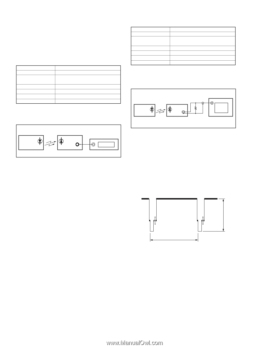
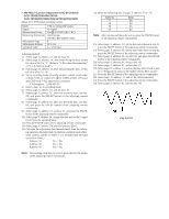
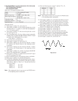
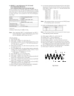
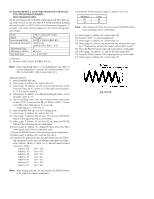
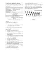
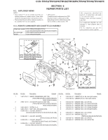
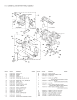
3-5. IR TRANSMITTER ADJUSTMENTS (CCD-TRV43/TRV46/TRV46PK) Adjust using a IR receiver jig (J-6082-383-A). Switch setting: LASER LINK Red LED is lit) 1. IR Video Carrier Frequency Adjustment (VC-215 board) Mode Subject Measurement Point Measuring Instrument Adjustment Page Adjustment Address Specified Value Camera standby Arbitrary Pin 5 of CN003 of IR receiver jig (RF) ( Or Pin !§ of IC751 of VC-215 board) Frequency counter F 68 f = 11.85±0.05MHz Connection of Equipment Connect the measuring device as shown in the following figure, and adjust. 2. IR Video Deviation Adjustment (VC-215 board) Mode Subject Measurement Point Measuring Instrument Adjustment Page Adjustment Address Specified Value Camera standby Arbitrary VIDEO OUT terminal of IR receiver jig (Terminated at 75Ω) Oscilloscope F 66 A = 0.87±0.04V Connection of Equipment Connect the measuring device as shown in the following figure, and adjust. Main unit IR receiver jig 75 Ω Oscilloscope VIDEO OUT 75 Ω (1-247-804-11) Main unit IR receiver jig Pin 5 of CN003 Frequency counter Fig. 5-3-17. Adjusting method: 1) Select page: 0, address: 01, and set data: 01. 2) Select page: 3, address: 01, set data: 37, and press the PAUSE button of the adjusting remote commander. 3) Select page: F, address: 68, change the data, and set the video carrier frequency (f) to the specified value. 4) Press the PAUSE button of the adjusting remote commander. 5) Select page: 3, address: 01, set data: 00, and press the PAUSE button of the adjusting remote commander. 6) Select page: 0, address: 01, and set data: 00. Fig. 5-3-18. Adjusting method: 1) Select page: 0, address: 01, and set data: 01. 2) Select page: 3, address: 01, set data: 39, and press the PAUSE button of the adjusting remote commander. 3) Select page: F, address: 66, and change the data, set the video signal amplitude (A) to the specified value. 4) Press the PAUSE button of the adjusting remote commander. 5) Select page: 3, address: 01, set data: 00, and press the PAUSE button of the adjusting remote commander. 6) Select page: 0, address: 01, and set data: 00. A H Fig. 5-3-19.
-
 1
1 -
2
-
3
-
4
-
5
-
6
-
7
-
8
-
9
-
10
-
11
-
12
-
13
-
14
-
15
-
16
-
17
-
18
-
19
-
20
-
21
-
22
-
23
-
24
-
25
-
26
-
27
-
28
-
29
-
30
-
31
-
32
-
33
-
34
-
35
-
36
-
37
-
38
-
39
-
40
-
41
-
42
-
43
-
44
-
45
-
46
-
47
-
48
-
49
-
50
-
51
-
52
-
53
-
54
-
55
-
56
-
57
-
58
-
59
-
60
-
61
-
62
-
63
-
64
-
65
-
66
-
67
-
68
-
69
-
70
-
71
-
72
-
73
-
74
-
75
-
76
-
77
-
78
-
79
-
80
-
81
-
82
-
83
-
84
-
85
-
86
-
87
-
88
-
89
-
90
-
91
-
92
-
93
-
94
-
95
-
96
-
97
-
98
-
99
-
100
-
101
-
102
-
103
-
104
-
105
-
106
-
107
-
108
-
109
-
110
-
111
-
112
-
113
-
114
-
115
-
116
-
117
-
118
-
119
-
120
-
121
-
122
-
123
-
124
-
125
-
126
-
127
-
128
-
129
-
130
-
131
-
 132
132 -
 133
133 -
 134
134 -
 135
135 -
 136
136 -
 137
137 -
 138
138 -
 139
139 -
 140
140 -
 141
141 -
 142
142 -
143
-
144
-
145
-
146
-
147
-
148
-
149
-
150
-
151
-
152
-
153
-
154
-
155
-
156
-
157
-
158
-
159
-
160
-
161
-
162
-
163
-
164
-
165
-
166
-
167
-
168
-
169
-
170
-
171
-
172
-
173
-
174
-
175
-
176
-
177
 |
 |