Sony CCD TRV16 Service Manual - Page 127
SERVO SYSTEM ADJUSTMENTS, CAP FG Offset Adjustment VC-215 board, RF Switching Position Adjustment VC
 |
UPC - 027242551497
View all Sony CCD TRV16 manuals
Add to My Manuals
Save this manual to your list of manuals |
Page 127 highlights
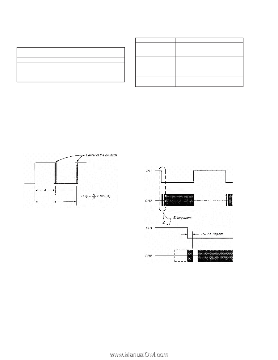
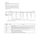
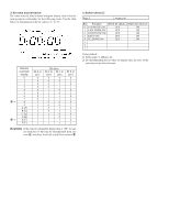
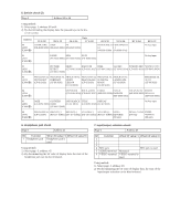
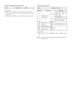
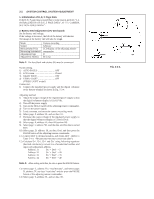
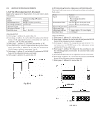
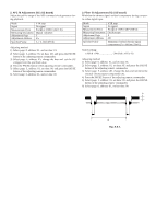
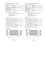
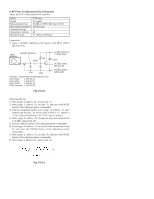
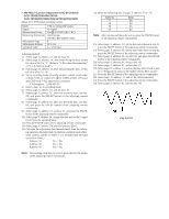
3-3. SERVO SYSTEM ADJUSTMENTS 1. CAP FG Offset Adjustment (VC-215 board) Improve the capstan servo characteristic. If it is not correct. jitters will increase. Mode Subject Measurement Point Measuring Instrument Adjustment Page Adjustment Address Specified value Camera recording (SP mode) Arbitrary Pin !™ of CN910 (CAP FG) Oscilloscope F 69 Duty = 50±0.5% Adjusting method: 1) Select page: 0, address: 01, and set data: 01. 2) Select page: 2, address: 01, and set data: 81, and press the PAUSE button of the adjustment remote commander. (to start up automatic CAP FG offset adjustment.) 3) Select page: 2, address: 02, and check that the data is "01". 4) Check that Duty of CAP FG signal satisfies the specified value. If not, select page: 2, address: 01, set data: 00, and press the PAUSE button, and then, repeat steps 2) to 4). 5) Select page: 2, address: 01, and set data: 00, and press the PAUSE button of the adjustment remote commander. 6) Select page: 0, address: 01, and set data: 00. 2. RF Switching Position Adjustment (VC-215 Board) If deviated in this case causes switching noise or jitter on the played back screen. Mode Signal Measurement Point Measuring Instrument Adjustment Page Adjustment Address Specified Value Playback Alignment tape: For tracking adjustment WR5-1NP CH1: Pin !¡ of CN910 (RF SWP) CH2: Pin 6 of CN910 (PB RF) Oscilloscope F 7C (upper digits), 7D (lower digits) t1 = 0±10µsec Adjusting Method: 1) Select page: 0, address: 01, and set data: 01. 2) Select page: F, address: 2A, and set data: 20, and press the PAUSE button of the adjustment remote commander. 3) Select page: F, address: 7C, change the data and minimize "t1", and then press the PAUSE button of the adjustment remote commander. (Coarse adjustment) 4) Select page: F, address: 7D, change the data and adjust so that the switching position (t1) becomes the specified value. (Fine adjustment) 5) Press the PAUSE button of the adjustment remote commander. 6) Select page: F, address: 2A, and set data: 00, and press the PAUSE button of the adjustment remote commander. 7) Select page: 0, address: 01, and set data: 00. Fig. 5-3-5. Fig. 5-3-6.
-
 1
1 -
2
-
3
-
4
-
5
-
6
-
7
-
8
-
9
-
10
-
11
-
12
-
13
-
14
-
15
-
16
-
17
-
18
-
19
-
20
-
21
-
22
-
23
-
24
-
25
-
26
-
27
-
28
-
29
-
30
-
31
-
32
-
33
-
34
-
35
-
36
-
37
-
38
-
39
-
40
-
41
-
42
-
43
-
44
-
45
-
46
-
47
-
48
-
49
-
50
-
51
-
52
-
53
-
54
-
55
-
56
-
57
-
58
-
59
-
60
-
61
-
62
-
63
-
64
-
65
-
66
-
67
-
68
-
69
-
70
-
71
-
72
-
73
-
74
-
75
-
76
-
77
-
78
-
79
-
80
-
81
-
82
-
83
-
84
-
85
-
86
-
87
-
88
-
89
-
90
-
91
-
92
-
93
-
94
-
95
-
96
-
97
-
98
-
99
-
100
-
101
-
102
-
103
-
104
-
105
-
106
-
107
-
108
-
109
-
110
-
111
-
112
-
113
-
114
-
115
-
116
-
117
-
118
-
119
-
120
-
121
-
 122
122 -
 123
123 -
 124
124 -
 125
125 -
 126
126 -
 127
127 -
 128
128 -
 129
129 -
 130
130 -
 131
131 -
 132
132 -
133
-
134
-
135
-
136
-
137
-
138
-
139
-
140
-
141
-
142
-
143
-
144
-
145
-
146
-
147
-
148
-
149
-
150
-
151
-
152
-
153
-
154
-
155
-
156
-
157
-
158
-
159
-
160
-
161
-
162
-
163
-
164
-
165
-
166
-
167
-
168
-
169
-
170
-
171
-
172
-
173
-
174
-
175
-
176
-
177
 |
 |