Sony CCD TRV16 Service Manual - Page 136
RECCurrent Adjustment VC-215 board, Note 1
 |
UPC - 027242551497
View all Sony CCD TRV16 manuals
Add to My Manuals
Save this manual to your list of manuals |
Page 136 highlights
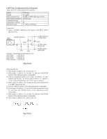
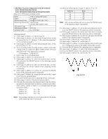
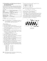
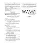
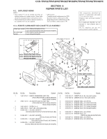
11. REC C Current Adjustment (VC-215 board) Set the recording current levels of the REC Chroma signal. If it is too low, chroma signal noise in played back picture will increased. If too high, Y signal noises will increase and white modulation noises will be produced. Mode Signal Measurement Point Measuring Instrument Adjustment Page Adjustment Address Specified Value VTR recording (SP mode) No signal Pin !º of CN910 (REC RF) Oscilloscope F 65 Hi8 model : A = 34.6±1.2mV Standard8 model : A = 30.0±1.1mV Note 1: Hi8 model: CCD- TR516/TR516PK/TR716 CCD- TRV36/TRV36PK/TRV43/TRV46/ TRV46PK Standard8 model: CCD-TR315/TR416/TR416PK CCD-TRV16/TRV16PK Connection: 1) Remove C085 (0.01µF, Pin !§ of IC202). Note: After completing "REC L Level Adjustment" and "REC C Current Adjustment", replace C085 with new parts (1-162970-11 CERAMIC CHIP 0.01µF 10% 25V). 2) Connect Pin 1 of IC001 and GND with a 0.01F capacitor. 0.01µF capacitor: 1-101-004-00 Adjusting method: 1) Select page: 0, address: 01, and set data: 01. 2) Select page: D, address: 14, after memorizing the data, set the bit value of bit1 to "1". (Refer to "3. Bit value discrimination" of "3-1-8. Service mode"). 3) Select page: D, address: 15, after memorizing the data , set the bit value of bit7 to "0". 4) Set to recording mode. (Use the wireless remote commander of 8mm VCR, or connect Pin 6 of CN935 of DD-117 board and GND with 4.7kΩ registor for a second.) 4.7kΩ registor : 1-249-425-11 5) Insert a tape, set to recording mode. 6) Select page: 0, address: 01, and set data: 01. 7) Select page: 3, address: 01, set data: 41, and press the PAUSE button of the adjusting remote commander. 8) Select page: 2, address: 61, and set data: 30. 9) Select page: F, address: 65, change the data and set the REC chroma signal level (A) to the specified value. 10) Press the PAUSE button of the adjusting remote commander. 11) Select page: 2, address: 61, and set data: 10. 12) Select page: 3, address: 01, set data: 00, and press the PAUSE button of the adjusting remote commander. 13) Select page: 0, address: 01, and set data: 00. 14) Select page: 0, address: 01, and set data: 01. 15) Select page: D, address: 14, and set the data memorized at step 2) of "Preparations only for the model without REC switch". 16) Press the PAUSE button of the adjusting remote commander. 17) Select page: D, address: 15, and set the data memorized. 18) Press the PAUSE button of the adjusting remote commander. 19) Select page: 0, address: 01, and set data: 00. Center of the luminance line width Fig. 5-3-16. A 1.35 µsec
-
 1
1 -
2
-
3
-
4
-
5
-
6
-
7
-
8
-
9
-
10
-
11
-
12
-
13
-
14
-
15
-
16
-
17
-
18
-
19
-
20
-
21
-
22
-
23
-
24
-
25
-
26
-
27
-
28
-
29
-
30
-
31
-
32
-
33
-
34
-
35
-
36
-
37
-
38
-
39
-
40
-
41
-
42
-
43
-
44
-
45
-
46
-
47
-
48
-
49
-
50
-
51
-
52
-
53
-
54
-
55
-
56
-
57
-
58
-
59
-
60
-
61
-
62
-
63
-
64
-
65
-
66
-
67
-
68
-
69
-
70
-
71
-
72
-
73
-
74
-
75
-
76
-
77
-
78
-
79
-
80
-
81
-
82
-
83
-
84
-
85
-
86
-
87
-
88
-
89
-
90
-
91
-
92
-
93
-
94
-
95
-
96
-
97
-
98
-
99
-
100
-
101
-
102
-
103
-
104
-
105
-
106
-
107
-
108
-
109
-
110
-
111
-
112
-
113
-
114
-
115
-
116
-
117
-
118
-
119
-
120
-
121
-
122
-
123
-
124
-
125
-
126
-
127
-
128
-
129
-
130
-
 131
131 -
 132
132 -
 133
133 -
 134
134 -
 135
135 -
 136
136 -
 137
137 -
 138
138 -
 139
139 -
 140
140 -
 141
141 -
142
-
143
-
144
-
145
-
146
-
147
-
148
-
149
-
150
-
151
-
152
-
153
-
154
-
155
-
156
-
157
-
158
-
159
-
160
-
161
-
162
-
163
-
164
-
165
-
166
-
167
-
168
-
169
-
170
-
171
-
172
-
173
-
174
-
175
-
176
-
177
 |
 |
