Sony DSR 45 Operating Instructions - Page 14
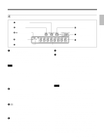
Monitor display CHARACTER DISPLAY LCD data items - parts
 |
UPC - 027242603998
View all Sony DSR 45 manuals
Add to My Manuals
Save this manual to your list of manuals |
Page 14 highlights
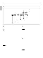
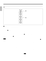
Chapter 1 Overview Location and Function of Parts - Audio recording level adjustment mode (AUTO/ MANU) - Audio mode (32 kHz/48 kHz) - Audio limiter - Color bars (Cannot be displayed) • If you change this selector, the screen may momentarily become bright or noise may appear. This noise will be recorded. • Do not change this selector setting during recording. Otherwise, the recorded image will be distorted or the signal output from the DV jack will be interrupted. Also, the unit may mistakenly recognize that a copyright protected signal has been input. qa EJECT (OPEN/CLOSE) (open/close the cassette compartment) button Press this button to open or close the cassette compartment. If you press this button while a cassette is inside the unit, the compartment opens and the cassette is ejected. After removing the cassette, press this button again to close the compartment. 1 Monitor display section 1 LCD monitor 2 CHARACTER DISPLAY (LCD) selector 3 DISPLAY SELECT selector 4 EXEC or FINE (AUDIO) button 5 J / j buttons 1 LCD (Liquid Crystal Display) monitor Displays the playback or EE1) pictures. Also, superimposed time data, status information, menu, audio levels meters, etc. are displayed. Notes • The data items superimposed on the LCD monitor are the same as items superimposed on a monitor connected to the MONITOR VIDEO jack. You cannot make two monitors display different data items individually. • The backlight used in the built-in LCD monitor deteriorates with prolonged use. If the brightness of the LCD monitor cannot be adjusted, consult your Sony dealer. For details on the maintenance of the LCD monitor, see page 99 (GB). 2 CHARACTER DISPLAY (LCD) (data items superimposed on the LCD monitor) selector Use to superimpose data items on the LCD monitor. OFF: No data items are superimposed except the tape label, title, data codes (camera data, and date/ time recorded by a camera). ON: Data items are superimposed. ON (BLACK BACK): Data items are displayed on a black background. ... 1) "EE" stands for "Electric to Electric." In EE mode, the video and audio signals that are input to the VCR's recording circuitry do not pass through any magnetic conversion circuits but instead are output via electric circuits only. This mode is used to check the input signals and adjust input levels. The pictures output in EE mode are referred to as EE pictures. 14 (GB) Chapter 1 Overview
-
 1
1 -
2
-
3
-
4
-
5
-
6
-
7
-
8
-
 9
9 -
 10
10 -
 11
11 -
 12
12 -
 13
13 -
 14
14 -
 15
15 -
 16
16 -
 17
17 -
 18
18 -
 19
19 -
20
-
21
-
22
-
23
-
24
-
25
-
26
-
27
-
28
-
29
-
30
-
31
-
32
-
33
-
34
-
35
-
36
-
37
-
38
-
39
-
40
-
41
-
42
-
43
-
44
-
45
-
46
-
47
-
48
-
49
-
50
-
51
-
52
-
53
-
54
-
55
-
56
-
57
-
58
-
59
-
60
-
61
-
62
-
63
-
64
-
65
-
66
-
67
-
68
-
69
-
70
-
71
-
72
-
73
-
74
-
75
-
76
-
77
-
78
-
79
-
80
-
81
-
82
-
83
-
84
-
85
-
86
-
87
-
88
-
89
-
90
-
91
-
92
-
93
-
94
-
95
-
96
-
97
-
98
-
99
-
100
-
101
-
102
-
103
-
104
-
105
-
106
-
107
-
108
-
109
-
110
-
111
-
112
-
113
-
114
-
115
-
116
-
117
-
118
-
119
-
120
-
121
-
122
-
123
-
124
-
125
-
126
-
127
-
128
-
129
-
130
-
131
-
132
-
133
-
134
-
135
-
136
-
137
-
138
-
139
-
140
-
141
-
142
-
143
-
144
-
145
-
146
-
147
-
148
-
149
-
150
-
151
-
152
-
153
-
154
-
155
-
156
-
157
-
158
-
159
-
160
-
161
-
162
-
163
-
164
-
165
-
166
-
167
-
168
-
169
-
170
-
171
-
172
-
173
-
174
-
175
-
176
-
177
-
178
-
179
-
180
-
181
-
182
-
183
-
184
-
185
-
186
-
187
-
188
-
189
-
190
-
191
-
192
-
193
-
194
-
195
-
196
-
197
-
198
-
199
-
200
-
201
-
202
-
203
-
204
-
205
-
206
-
207
-
208
-
209
-
210
-
211
-
212
-
213
-
214
-
215
-
216
-
217
-
218
-
219
-
220
 |
 |
