Sony DSR 45 Operating Instructions - Page 27
Displaying Various Data - dvcam vtr
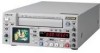 |
UPC - 027242603998
View all Sony DSR 45 manuals
Add to My Manuals
Save this manual to your list of manuals |
Page 27 highlights
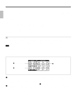
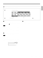
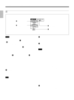
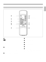
Displaying Various Data Chapter 1 Overview The unit can display various superimposed data items on the built-in LCD monitor or on a monitor connected to the MONITOR VIDEO jack. To display various data items on the LCD monitor, set the CHARACTER DISPLAY (LCD) selector to ON or ON (BLACK BACK). To display various data items on an external monitor, set the CHARACTER DISPLAY (MONITOR OUT) switch to ON. You can select data items to be displayed using the DISPLAY SELECT selector. Menu screen To display the menu screen, set the DISPLAY SELECT selector to MENU. You can change or confirm the menu item settings on this screen. For details on the menu, see "Chapter 6 Adjusting and Setting Through Menus" on page 76 (GB). TC ⁄ UB SET TC TC PRESET RMT UB PRESET CM TC ⁄ UB IN DISP DV IN TC V TC MAKE A TC RUN VTR TC FORMAT ETC JOG TC OUT Data screen To display the data screen, set the DISPLAY SELECT selector to DATA. You can confirm important information for recording or playback, such as time code or remaining tape time, on this screen. 2 3 1 N TC 0 0 : 1 2 : 3 4 : 1 2 4 122min PHOTO -10 5,6 SEARCH %Z 7 DEW DETECTED 8 PAL DVCAM 9 NS 48K DV I N q; qa qs 1 Cassette memory indicator This item is shown when a cassette with cassette memory has been loaded. If the cassette is ejected while data is being written on the cassette memory, the indicator flashes. 2 Tape transport mode indicator Displays the tape transport mode. 3 Time counter (time code/user bits/count value of the counter) indicator Displays the count value of the counter, time code, or user bits. By setting the COUNTER SELECT selector on the front panel, you can select the item to be displayed. When the time code is displayed, TC appears to its left. In the drop frame mode, a period is displayed between the minutes and seconds. (Example: 00:12.58:00) When the user bits are displayed, UB appears to their left. When the count value of the counter is negative, "-" appears as the first digit (leftmost digit). When that value is positive, the first digit is blank. The count value of the counter consists of seven digits. If the self-diagnostic function is enabled, diagnostics code numbers are displayed. Notes • The counter operates on a ±12-hour cycle. You cannot make the counter operate on a 24-hour cycle. • The count value of the counter consists of seven digits. The leftmost digit is not displayed. (i.e.; If the actual count value is "11:22:11:22," the displayed value will be "1:22:11:22." ) However, the unit recognizes that the hours value is 11. 4 Remaining tape time indicator Displays the remaining tape time. Note When you insert a cassette in which the tape has been rewound to the beginning, this indicator will not show the remaining tape time. The remaining tape time is displayed after the tape runs for a while. 5 Search indicator Displays the search mode when you search for scenes using the Remote Commander or the DSRM-20 (not supplied). For details on the search function, see "Searching using the search function" on page 37 (GB). (Continued) 27 Chapter 1 Overview (GB)
-
 1
1 -
2
-
3
-
4
-
5
-
6
-
7
-
8
-
9
-
10
-
11
-
12
-
13
-
14
-
15
-
16
-
17
-
18
-
19
-
20
-
21
-
 22
22 -
 23
23 -
 24
24 -
 25
25 -
 26
26 -
 27
27 -
 28
28 -
 29
29 -
 30
30 -
 31
31 -
 32
32 -
33
-
34
-
35
-
36
-
37
-
38
-
39
-
40
-
41
-
42
-
43
-
44
-
45
-
46
-
47
-
48
-
49
-
50
-
51
-
52
-
53
-
54
-
55
-
56
-
57
-
58
-
59
-
60
-
61
-
62
-
63
-
64
-
65
-
66
-
67
-
68
-
69
-
70
-
71
-
72
-
73
-
74
-
75
-
76
-
77
-
78
-
79
-
80
-
81
-
82
-
83
-
84
-
85
-
86
-
87
-
88
-
89
-
90
-
91
-
92
-
93
-
94
-
95
-
96
-
97
-
98
-
99
-
100
-
101
-
102
-
103
-
104
-
105
-
106
-
107
-
108
-
109
-
110
-
111
-
112
-
113
-
114
-
115
-
116
-
117
-
118
-
119
-
120
-
121
-
122
-
123
-
124
-
125
-
126
-
127
-
128
-
129
-
130
-
131
-
132
-
133
-
134
-
135
-
136
-
137
-
138
-
139
-
140
-
141
-
142
-
143
-
144
-
145
-
146
-
147
-
148
-
149
-
150
-
151
-
152
-
153
-
154
-
155
-
156
-
157
-
158
-
159
-
160
-
161
-
162
-
163
-
164
-
165
-
166
-
167
-
168
-
169
-
170
-
171
-
172
-
173
-
174
-
175
-
176
-
177
-
178
-
179
-
180
-
181
-
182
-
183
-
184
-
185
-
186
-
187
-
188
-
189
-
190
-
191
-
192
-
193
-
194
-
195
-
196
-
197
-
198
-
199
-
200
-
201
-
202
-
203
-
204
-
205
-
206
-
207
-
208
-
209
-
210
-
211
-
212
-
213
-
214
-
215
-
216
-
217
-
218
-
219
-
220
 |
 |
