Sony HDW1800 Installation Manual
Sony HDW1800 Manual
 |
View all Sony HDW1800 manuals
Add to My Manuals
Save this manual to your list of manuals |
Sony HDW1800 manual content summary:
- Sony HDW1800 | Installation Manual - Page 1
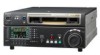
HD DIGITAL VIDEOCASSETTE RECORDER HDW-1800 HDW-D1800 INSTALLATION MANUAL 1st Edition - Sony HDW1800 | Installation Manual - Page 2
! WARNING This manual is intended for qualified service personnel only. To reduce the risk of electric shock, fire or injury, do not perform any servicing other than that contained in the operating instructions unless you are qualified to do so. Refer all servicing to qualified service personnel. ! - Sony HDW1800 | Installation Manual - Page 3
equivalent type recommended by the manufacturer. Dispose of used batteries according to the manufacturer's instructions. Vorsicht! Explosionsgefahr bei unsachgemäßem Austausch der laitevalmistajan suosittelemaan tyyppiin. Hävitä käytetty paristo valmistajan ohjeiden mukaisesti. HDW-1800/D1800 1 (P) - Sony HDW1800 | Installation Manual - Page 4
equipment while taking the operating temperature of the equipment into consideration For the operating temperature of the equipment, refer to the specifications of the Operation Manual. 6. When performing in als klein chemisch afval (KCA). For the customers in Taiwan only 2 (P) HDW-1800/D1800 - Sony HDW1800 | Installation Manual - Page 5
Contents Manual Structure Purpose of this manual 2 (E) Related manuals 2 (E) 1. Installation 1-1. Installation Procedure 1-1 (E) 1-2. Supplied Accessories 1-1 (E) 1-3. Operating Conditions 17. Taking Out the Cassette in Tape Slacking 1-23 (E) Appendix A Setting Check Sheet HDW-1800/D1800 1 (E) - Sony HDW1800 | Installation Manual - Page 6
Assignments" CD-ROM allows you to search for semiconductors used in Broadcast and Professional equipment. The maintenance manual (volume-2) contains a complete list of semiconductors and their ID Nos., and thus should be used together with the CD-ROM. Part number: 9-968-546-0X 2 (E) HDW-1800/D1800 - Sony HDW1800 | Installation Manual - Page 7
operation manual. (For more details, refer to the maintenance manual volume-1.) End . Screws for rack mounting (PSW 4 x 16 4 . Operation guide 1 . Operation manual CD-ROM (PDF 1 . Installation manual 1 1-3. Operating when the unit is operat- ed at not-horizontal place. HDW-1800/D1800 1-1 (E) - Sony HDW1800 | Installation Manual - Page 8
This unit's power line has a switching regulator. c Be sure to operate the unit within the range of following power voltage. Power voltage: AC 783-481-42 3-613-640-01 AC inlet If the unit is used in the area except above, please contact your local Sony Sales Office/Service Center. HDW-1800/D1800 - Sony HDW1800 | Installation Manual - Page 9
and right sides. Leaving 40 centimeters or more of space above the unit is recommended for service operation. Moreover, an air flow that is effective in cooling the unit is essential. If the ventilation .5 415.9 48 457.5 Dimensions when Rack-Mounting (38.5) Unit : mm HDW-1800/D1800 1-3 (E) - Sony HDW1800 | Installation Manual - Page 10
the bottom plate of the unit. 3. Set the unit in a horizontal position. Feet PS4 x 20 Feet PS4 x 20 n Keep these screws and the feet. When operating the unit after demounting it from the rack, be sure to reattach the feet. Tightening torque: 98 x 10_2 N . m {10 kgf . cm} HDW-1800/D1800 - Sony HDW1800 | Installation Manual - Page 11
-130, use the supplied screws PSW4 x 16 as shown in Fig. 1. Inner rail B4 x 6 Rack angle PSW4 x 16 n When replacing a 5U size Sony VTR with this unit, attach the inner rails to the low position, so that the bottom of the unit becomes same as that of the 5U size VTR. HDW-1800/D1800 - Sony HDW1800 | Installation Manual - Page 12
(B4 x 8) fixing the four rail brackets. Tightening torque: 120 x 10_2 N . m {12.2 kgf . cm} Rack Rail bracket Outer rail 50 to 55 mm Rack angle B4 x 8 1-6 (E) HDW-1800/D1800 - Sony HDW1800 | Installation Manual - Page 13
the eight loosely fitted hexagon socket head cap screws in step 12 using the L-shaped hexagon wrench. 18. Pull equal length of each rail catch your finger or hand in rack mount rail. Release button Stopper HDW-1800/D1800 Intermediate rail Stopper Inner rail Release button n Pushing the unit - Sony HDW1800 | Installation Manual - Page 14
does not have the feet at this operating. Put down the unit on the sure to fix the unit to the rack using the screws and ornamental washers supplied with the guide for more detailed information. Release button Ornamental washer RK5 x 14 RK5 x 14 Release button Ornamental washer 1-8 (E) HDW-1800 - Sony HDW1800 | Installation Manual - Page 15
(or equivalents) must be used. Panel indication AUDIO INPUT TIME BNC 75Z, MALE *3 JM-60 stereo phone plug Sony part No. 1-508-084-00 1-508-083-00 1- 600 meters (Reference value based on HDW series) It is recommended to connect the meters (Reference value based on HDW series) It is recommended to - Sony HDW1800 | Installation Manual - Page 16
(RS-232C interface) for ISR (Interactive Status Reporting) 4 VIDEO CONTROL (9P) D-SUB 9P connector for a TBC remote controller (HKDV-900) connection *** : Refer to Optional "Interface manual" for details. 1-10 (E) HDW-1800/D1800 - Sony HDW1800 | Installation Manual - Page 17
& ITU-R BT.656 JM-60 stereo phone jack Analog audio up to _12 dBu (8 Z load), unbalanced Memory stick x 1 Applicable memory stick (8 MB to 128 MB) HDW-1800/D1800 1-11 (E) - Sony HDW1800 | Installation Manual - Page 18
DATA RESET REMOTE2 SETTING DATA RESET STATUS ALL REC INHIBIT ALL REC INHIBIT STATUS GND PLAY CLOSURE SW (PLAY) STOP CLOSURE SW (STOP) (Continue) 1-12 (E) HDW-1800/D1800 - Sony HDW1800 | Installation Manual - Page 19
V or open) *2: The pins described as O mark are possible to change the setting. Refer to the optional interface manual for changing the setting. REMOTE1-IN: 9-pin (female) REMOTE1-OUT: 9-pin (female) External view 5 1 Pin No Send (Output) CTS ; Clear to Send (Input) NC HDW-1800/D1800 1-13 (E) - Sony HDW1800 | Installation Manual - Page 20
Connector Panel When the unit is installed, be sure to perform the following setup. Refer to the operation manual "Section 2 Location and Function of Parts" for setup. . Analog audio input level/600 Z termination switches . 75 Z termination switch of reference video input 1-14 (E) HDW-1800/D1800 - Sony HDW1800 | Installation Manual - Page 21
Boards 1-10-1. APR-80 Board If necessary, perform the following audio-related settings using the switches on the APR-80 board. . Audio input, output, and monitor E F G H J APR-80 K L M N P 1 S1901 S1900 A S1902 2 S2001 S2000 3 4 5 6 APR-80 Board (Side A) HDW-1800/D1800 1-15 (E) - Sony HDW1800 | Installation Manual - Page 22
the level is adjusted with the PHONES level control knob. Channel L Ref. No. S2001 R S2000 Switch state (\ : Knob position) Fixed 1 O 2 N (Factory setting) Variable 1 O 2 N Factory use n Never change the setting. Ref. No. S1900, S1901 Switch state All OFF 1-16 (E) HDW-1800/D1800 - Sony HDW1800 | Installation Manual - Page 23
. 1-11-1. Operation Procedure of Destination HDW-1800/D1800 Screen 2 About 10 seconds DESTINATION SET COMPLETE 59.94:SYL TURN OFF/ON POWER !! To return the destination to the "NO-SET" status: Reset all the unit settings to the factory settings using "M49: RESET ALL SETUP" of the maintenance - Sony HDW1800 | Installation Manual - Page 24
unit Reattaching Reattach the lower control panel unit in the reverse order of removal. Yet when reattaching, use care about following points. . If the arms are not open, press the both side of unlock buttons visible from your side before tightening the screws. Connector 1-18 (E) HDW-1800/D1800 - Sony HDW1800 | Installation Manual - Page 25
Unlock button Round hole The shaft is not seen. Allowing Search Dial Pressing 1. Open the lower control panel. (Operation side up) 2. Loosen a screw on the backside of the search dial as shown in the figure. 3. Search dial shaft Round hole The shaft is seen. Portion A HDW-1800/D1800 1-19 (E) - Sony HDW1800 | Installation Manual - Page 26
the setting of setup menu ITEM-309, and the operation mode (PB/EDIT/REC) of this unit. (Refer to the table 1-14-1 below.) m . To select the video input, use F1 (VIDEO IN) in the function menu page P01 input video signal is selected by the video input selection. INPUT ----- 1-20 (E) HDW-1800/D1800 - Sony HDW1800 | Installation Manual - Page 27
(BVE-2000, etc.) Capable of the 1st Edit When this unit is used by connecting to an editor, set as follows. Button F1 F2 F3 Item MODE AFTER CUE-UP to "STOP". Model HDW-1800, HDW-D1800 Table 1-15-2. VTR Constant Values Settings of Editor Operation VTR CONSTANT 1 VTR CONSTANT 2 Mode Data - Sony HDW1800 | Installation Manual - Page 28
-in board is replaced, refer to the mainte- nance manual, volume-1. Removing 1. Fully loosen the two fixing screws. 2. Remove the upper lid (rear) assembly by moving in the direction indicated by the arrow. Screw with stopper Upper lid (rear) assembly Screw with stopper 1-22 (E) HDW-1800/D1800 - Sony HDW1800 | Installation Manual - Page 29
the outside to fix the upper lid (front) assembly. 4. Remove the upper lid (front) assembly. Knob Upper lid (front) assembly Fixing screw Knob Removal Installation HDW-1800/D1800 1-23 (E) - Sony HDW1800 | Installation Manual - Page 30
Check by eye that the unit is in the state to be able to wind manually the tape. 7. Pull the ME wire for a few times with short steps Be careful for the tape not to catch in parts such as a flange of a tape guide. . Don't take the ME wire off the wire holder. . The ME wire links (E) HDW-1800/D1800 - Sony HDW1800 | Installation Manual - Page 31
HOURS (Resettable) H13: TAPE RUNNING HOURS (Resettable) H14: THREADING COUNTER (Resettable) Date Hours meter n The current settings of setup menu can be saved and read using a Memory Stick. For details, refer to the maintenance manual volume 1. HDW-1800/D1800 A-1 (E) - Sony HDW1800 | Installation Manual - Page 32
reference level Monitor output level FIXED/VARIABLE switch Factory use Factory use Factory use Factory use Channel CH1 CH2 CH1/2/L/R CH1/2 CH1/CH2 0 [||] +4 [||] 0 [||] Fixed [||] Fixed _ _ _ _ [||] _3 [||] _20 [||] _3 [||] _20 [||] _3 [||] _20 [||] Variable [||] Variable A-2 (E) HDW-1800/D1800 - Sony HDW1800 | Installation Manual - Page 33
1 : Factory use OFF _ 2 - 6 : Model ID switch See below. _ 7 : J/SY ON _ 8 : 525/625 OFF 1 : EXTENDED MENU ON 2 : MAINTENANCE MODE ACCESS ENABLE ON 3 - 8 : Factory use OFF _ S1501 factory setting ( \ : Knob position) HDW-1800 ON HDW-D1800 ON 1 8 1 8 HDW-1800/D1800 A-3 (E) - Sony HDW1800 | Installation Manual - Page 34
PHAS (50i, 25PsF, 23.98PsF, 24PsF mode) *2: SETUP LV (59.94i, 29.97PsF mode) /BLK LEVL (50i, 25PsF, 23.98PsF, 24PsF mode) [||] OFF [||] OFF [||] REMAIN A-4 (E) HDW-1800/D1800 - Sony HDW1800 | Installation Manual - Page 35
F6 INS VID F7 INS A1 F8 INS A2 F9 INS A3 F10 INS A4 Factory setting Setting _ _ _ _ _ _ _ _ _ _ _ _ _ OFF _ _ _ _ OFF _ _ OFF ON [||] RECDER [||] PLAYER [||] OFF HDW-1800/D1800 A-5 (E) - Sony HDW1800 | Installation Manual - Page 36
P101 : AUD MONI R CH-1 only CH-1 only [||] CH-1 [||] CH-5 [||] CUE [||] CH-1 [||] CH-5 [||] CUE [||] CH-2 [||] CH-6 [||] CH-2 [||] CH-6 [||] CH-3 [||] CH-7 [||] CH-3 [||] CH-7 [||] CH-4 [||] CH-8 [||] CH-4 [||] CH-8 A-6 (E) HDW-1800/D1800 - Sony HDW1800 | Installation Manual - Page 37
of this manual or the use thereof for any purpose other than the operation or maintenance of the equipment described in this manual without the express written permission of Sony Corporation. beschriebenen Ausrüstung ohne ausdrückliche schriftliche Erlaubnis der Sony Corporation. HDW-1800/D1800 - Sony HDW1800 | Installation Manual - Page 38
HDW-1800 (SY) HDW-1800 (CN) HDW-D1800 (SY) HDW-D1800 (CN) J, E 3-992-809-01 Sony Corporation Printed in Japan 2006. 9 08 ©2006
-
 1
1 -
 2
2 -
 3
3 -
 4
4 -
 5
5 -
 6
6 -
 7
7 -
8
-
9
-
10
-
11
-
12
-
13
-
14
-
15
-
16
-
17
-
18
-
19
-
20
-
21
-
22
-
23
-
24
-
25
-
26
-
27
-
28
-
29
-
30
-
31
-
32
-
33
-
34
-
35
-
36
-
37
-
38
 |
 |
INSTALLATION MANUAL
1st Edition
HD DIGITAL VIDEOCASSETTE RECORDER
HDW-1800
HDW-D1800