Sony HDW1800 Installation Manual - Page 16
Signal Inputs and Outputs
 |
View all Sony HDW1800 manuals
Add to My Manuals
Save this manual to your list of manuals |
Page 16 highlights
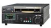
1-8. Signal Inputs and Outputs Reduced drawing of rear panel 3 1 2 5 6 4 Input connectors 1 AUDIO INPUT 1 TIME CODE IN 2 REF. INPUT 3 AUDIO INPUT (AES/EBU) 5 HD SDI INPUT 6 HDV IN (OPTION) XLR 3-pin x 2 (1 set : CH1, CH2) Analog audio LOW OFF : _60 dBu, high impedance, balanced HIGH OFF : +4 dBu (Standard), high impedance, balanced HIGH ON : +4 dBm (Standard), 600 Z termination, balanced XLR 3-pin x 1 Time code 0.5 to 18 V p-p, 10 kZ, balanced BNC x 2 in loop through connection Outside reference video signal SD : 0.3 V p-p, 75 Z, sync negative (Black burst or composite sync) HD : 0.6 V p-p, 75 Z, sync negative (Ternary SYNC) BNC x 2 (1 set : CH1/2, CH3/4) Digital audio AES/EBU format, complies with AES-3id-1995 BNC x 1 Serial digital interface (1.485 Gbit/s), complies with SMPTE 292M i.LINK 6-pin x 1 Complies with IEEE1394 Remote connectors 4 REMOTE 2 PARALLEL I/O (50P) *** D-SUB 50P connector 4 REMOTE1-IN (9P) D-SUB 9P connector (RS-422A interface), Remote control 4 REMOTE1-OUT (9P) D-SUB 9P connector (RS-422A interface), Remote control 4 RS-232C D-SUB 9P connector (RS-232C interface) for ISR (Interactive Status Reporting) 4 VIDEO CONTROL (9P) D-SUB 9P connector for a TBC remote controller (HKDV-900) connection *** : Refer to Optional "Interface manual" for details. 1-10 (E) HDW-1800/D1800
-
 1
1 -
2
-
3
-
4
-
5
-
6
-
7
-
8
-
9
-
10
-
 11
11 -
 12
12 -
 13
13 -
 14
14 -
 15
15 -
 16
16 -
 17
17 -
 18
18 -
 19
19 -
 20
20 -
 21
21 -
22
-
23
-
24
-
25
-
26
-
27
-
28
-
29
-
30
-
31
-
32
-
33
-
34
-
35
-
36
-
37
-
38
 |
 |
