Sony KLV-S32A10 Instructions (SU-WL31 Wall-Mount Bracket) - Page 7
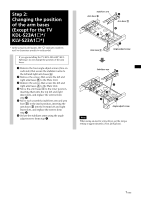
Step 2: Changing the position of the arm bases (Except for the TV KDL-S23A1s*/ KLV-S23A1s - specifications
 |
View all Sony KLV-S32A10 manuals
Add to My Manuals
Save this manual to your list of manuals |
Page 7 highlights
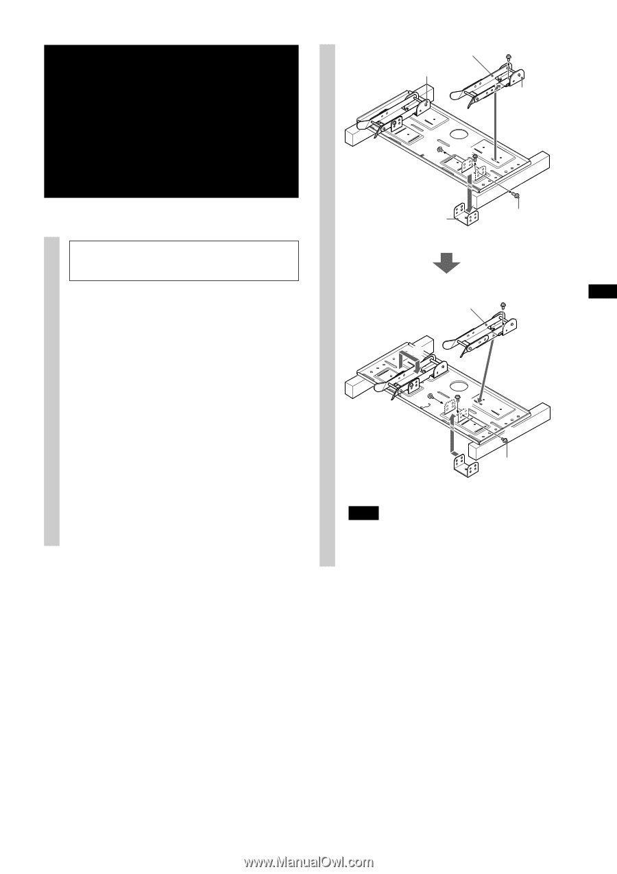
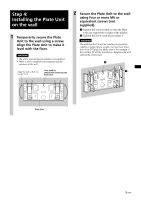
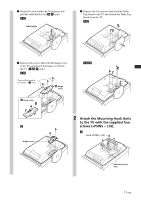
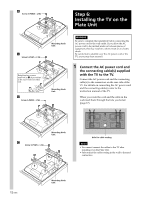
Step 2: Changing the position of the arm bases (Except for the TV KDL-S23A1s*/ KLV-S23A1s*) * In the actual model names, the "s" indicates numbers and/or characters specific to each model. If you are installing the TV KDL-S23A1s*/KLVS23A1s*, do not change the position of the arm bases. 1 Remove the four angle adjust screws (two on each side) that secure the stabilizer arms to the left and right arm bases A. 2 Remove the screws that secure the left and right arm bases B to the Plate Unit. 3 Remove the screws that secure the left and right arm bases A to the Plate Unit. 4 Move the arm bases A to the inner position, inserting them into the top left and right inner slots, and replace the screws from step 3. 5 Move each assembly (stabilizer arm and arm base B) to the inner position, inserting the arm bases B into the bottom left and right Inner slots, and replace the screws from step 2. 6 Secure the stabilizer arms using the angle adjust screws from step 1. Stabilizer arm Arm base B 2 Arm base B 2 13 Arm base A 1 Angle adjust screw Stabilizer arm 5 5 5 6 4 4 6 Angle adjust screw Note When using an electric screwdriver, set the torque setting to approximately 2 N·m {20 Kgf·cm}. 7 (GB)
-
 1
1 -
 2
2 -
 3
3 -
 4
4 -
 5
5 -
 6
6 -
 7
7 -
 8
8 -
 9
9 -
 10
10 -
 11
11 -
 12
12 -
13
-
14
-
15
-
16
-
17
-
18
-
19
-
20
-
21
-
22
-
23
-
24
-
25
-
26
-
27
-
28
-
29
-
30
-
31
-
32
-
33
-
34
-
35
-
36
-
37
-
38
-
39
-
40
-
41
-
42
-
43
-
44
-
45
-
46
-
47
-
48
-
49
-
50
-
51
-
52
-
53
-
54
-
55
-
56
-
57
-
58
-
59
-
60
-
61
-
62
-
63
-
64
-
65
-
66
-
67
-
68
-
69
-
70
-
71
-
72
-
73
-
74
-
75
-
76
-
77
-
78
-
79
-
80
-
81
-
82
-
83
-
84
-
85
-
86
-
87
-
88
-
89
-
90
-
91
-
92
-
93
-
94
-
95
-
96
-
97
-
98
-
99
-
100
 |
 |