Sony VPL EX5 User Manual - Page 57
Notes for VPL-EW5 - vpl ex50 ceiling mount
 |
UPC - 027242737334
View all Sony VPL EX5 manuals
Add to My Manuals
Save this manual to your list of manuals |
Page 57 highlights
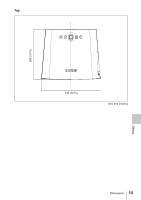
VPL-EX50/EX5/ES5 PS 40 a' N 1200 (47 1/4) M 1350 (53 1/4) x b 60 1800 (70 7/8) 2040 (80 3/8) 80 100 120 150 180 200 2410 (95) 3010 3620 4530 5440 6040 (118 5/8) (142 5/8) (178 3/8) (214 1/4) (237 7/8) 2720 3410 4090 5120 6140 6830 (107 1/8) (134 3/8) (161 1/8) (201 5/8) (241 7/8) (269) Based on the calculation formula given below. Free Unit: mm (inches) 250 300 7560 (297 3/4) 8540 (336 3/8) 9070 (357 1/4) 10250 (403 5/8) a'(N) = {(PS × 29.415) × 1.03} - 32.0 + 16.4 a'(M) = {(PS × 35.283) × 0.97} - 32.0 + 16.4 x = b + {PS × 5.073 + (a'+ 32.0 - 16.4) × 0.07344 - 2.3 + 72.5} VPL-EW5 (When "Aspect" on the Signal menu is set to "Full 2") PS 40 a' N 1270 (50) M 1430 (56 3/8) x b 60 1910 (75 1/4) 2160 (85 1/8) 80 100 120 150 180 200 2550 3190 3830 4800 (100 1/2) (125 5/8) (150 7/8) (189) 5760 6400 (226 7/8) (252) 2880 3610 4330 5420 (113 1/2) (142 1/4) (170 1/2) (213) 6510 7230 (256 3/8) (284 3/4) Based on the calculation formula given below. Free Unit: mm (inches) 250 300 8000 (315) 9050 (356 3/8) 9610 (378 1/2) 10860 (427 5/8) a'(N) = {(PS × 31.147) × 1.03} - 32.0 + 16.4 a'(M) = {(PS × 37.367) × 0.97} - 32.0 + 16.4 x = b + {PS × 4.481 + (a'+ 32.0 - 16.4) × 0.07344 - 2.3 + 72.5} Notes for VPL-EW5 • The projected image size is the one when "Aspect" on the Signal menu is set to "Full 2". When "Aspect" on the Signal menu is set to other than "Full 2", black bands may appear at the top and bottom or right and left of the screen. • When "Aspect" in the Signal menu is set to "4:3", the projected image size (diagonal) will be approximately 88 % of "Full 2" size. • When "Aspect" in the Signal menu is set to "16:9", the projected image size (diagonal) will be approximately 97 % of "Full 2" size. The alphabetical letters in the charts and calculation methods indicate the following. PS: projected image size measured diagonally (inches) a': distance between the hole (front) for mounting a projector suspension support on bottom surface of this projector and the center of the screen b: distance between the projector suspension support mounting surface on bottom of this projector and the ceiling x: distance between the center of the screen and the ceiling N: minimum M: maximum Others Installation Diagram 57
-
 1
1 -
2
-
3
-
4
-
5
-
6
-
7
-
8
-
9
-
10
-
11
-
12
-
13
-
14
-
15
-
16
-
17
-
18
-
19
-
20
-
21
-
22
-
23
-
24
-
25
-
26
-
27
-
28
-
29
-
30
-
31
-
32
-
33
-
34
-
35
-
36
-
37
-
38
-
39
-
40
-
41
-
42
-
43
-
44
-
45
-
46
-
47
-
48
-
49
-
50
-
51
-
 52
52 -
 53
53 -
 54
54 -
 55
55 -
 56
56 -
 57
57 -
 58
58 -
 59
59 -
 60
60 -
 61
61 -
 62
62
 |
 |
