TEAC AP-701 Owners Manual English Francais Espanol - Page 7
Names and functions of parts back
 |
View all TEAC AP-701 manuals
Add to My Manuals
Save this manual to your list of manuals |
Page 7 highlights
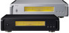
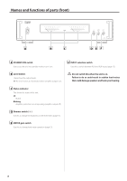
Names and functions of parts (back) EN A SPEAKER terminals Speakers that have nominal impedances between 4 Ω and 8 Ω are supported. Use commercially-available speaker cables to connect the speakers. B Analog audio input (INPUTS) connectors Use these to input stereo analog audio. Connect these connectors to the audio output connectors of a preamplifier or another device such as a DAC that has a preamplifier function. oo This unit's XLR connectors are 2: HOT. Use commercially-available audio cables for connections. RCA: RCA cables XLR: XLR cables OUTPUT MODE switch This sets the output mode. STEREO: stereo power amplifier (page 9) BI-AMP: mono bi-amplifier (page 10) VVAlways disconnect speakers before changing the output mode. Reconnect the speakers after changing the mode. Using with STEREO output mode Connect this unit's R input connector to the R output connector of the audio output device, and this unit's L input connector to the L output connector of the other device (page 9). Using with BI-AMP output mode Connect this unit's L connector to the L or R connector of the audio output device. The R connector of this device is not used (page 10). C 12V TRIGGER connectors Use these to control power from an external source. Do not connect anything to these connectors when not using them (page 11). Use commercially-available mono mini plug cables for connections. D SOFTWARE maintenance port This is used for maintenance. Do not connect anything to this port unless instructed to do so by our service department. E AUTO POWER SAVE switch This unit has an automatic power saving function. If the automatic power saving function is set to on, the unit will automatically enter standby mode if there is no audio input for about 30 minutes. F Power inlet (~IN) Connect the supplied power cord here. After all other connections are complete, connect the power cord's plug to a wall outlet. VVDo not use any power cord other than the one included with this unit. Use of other power cords could result in fire or electric shock. VVUnplug the cord from the outlet when not using the unit for a long time. 7
-
 1
1 -
 2
2 -
 3
3 -
 4
4 -
 5
5 -
 6
6 -
 7
7 -
 8
8 -
 9
9 -
 10
10 -
 11
11 -
 12
12 -
13
-
14
-
15
-
16
-
17
-
18
-
19
-
20
-
21
-
22
-
23
-
24
-
25
-
26
-
27
-
28
-
29
-
30
-
31
-
32
-
33
-
34
-
35
-
36
-
37
-
38
-
39
-
40
-
41
-
42
-
43
-
44
-
45
-
46
-
47
-
48
 |
 |
