TP-Link RPS150 RPS150 V1 IG
TP-Link RPS150 Manual
 |
View all TP-Link RPS150 manuals
Add to My Manuals
Save this manual to your list of manuals |
TP-Link RPS150 manual content summary:
- TP-Link RPS150 | RPS150 V1 IG - Page 1
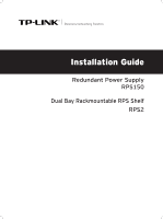
Business Networking Solution Installation Guide Redundant Power Supply RPS150 Dual Bay Rackmountable RPS Shelf RPS2 - TP-Link RPS150 | RPS150 V1 IG - Page 2
- TP-Link RPS150 | RPS150 V1 IG - Page 3
without permission from TP-LINK TECHNOLOGIES CO., LTD. Copyright © 2014 TP-LINK TECHNOLOGIES CO., LTD. All rights reserved. http://www.tp-link.com FCC and, if not installed and used in accordance with the instruction manual, may cause harmful interference to radio communications. Operation of this - TP-Link RPS150 | RPS150 V1 IG - Page 4
http://www.tp-link.com About this Installation Guide This Installation Guide describes the hardware RPS150. Appendix A Specifications. Appendix B Technical Support. Audience This Installation Guide is for: Network Engineer Network Administrator Conventions This Installation Guide is shared by RPS150 - TP-Link RPS150 | RPS150 V1 IG - Page 5
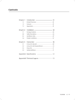
07 Chapter 3 3.1 3.2 3.3 3.4 Connection 09 Connect to Ground 09 Connect to the Powered Device 10 Power On 11 Verify Installation 11 Appendix A Specifications ---------- 12 Appendix B Technical Support --------- 13 Contents III - TP-Link RPS150 | RPS150 V1 IG - Page 6
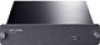
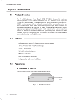
Redundant Power Supply CCCCCCCCCC Introduction 1111 Product Overview The TP-LINK Redundant Power Supply (RPS) RPS150 is designed to maximize availability for the business network. RPS150 is used as a redundant power supply for TP-LINK RPS capable L2 and L3 Managed switches. When worked with these - TP-Link RPS150 | RPS150 V1 IG - Page 7
information, please refer to section 3.1 Connect to Ground. Protective Cover It is used to protect the DC Power Output Socket. Remove it to connect RPS150 to the powered device. Caution: ■■ Please use the provided power cord and verify the power supply is 100-240V~50/60Hz. ■■ The electrical outlet - TP-Link RPS150 | RPS150 V1 IG - Page 8
appearance of RPS2 is shown as the following figure. RPS Slot FFFFFFFFFFF Appearance of RPS2 RPS Slot To install RPS150 into RPS2, please insert RPS150 into the RPS Slot. Each RPS2 is designed to hold up to 2 RPS150. For detail instructions, please refer to 2.4 Product Installation. 03 Introduction - TP-Link RPS150 | RPS150 V1 IG - Page 9
following items. If any of the listed items is damaged or missing, please contact your distributor. One RPS150 One DC Power Cord and one AC Power Cord This Installation Guide RPS150 RPS2 Four fittings 2222 Safety Precautions To avoid any device damage and bodily injury caused by improper use - TP-Link RPS150 | RPS150 V1 IG - Page 10
, mechanical property changes and corrosions. Too high temperature may accelerate aging of the insulation materials and can thus significantly shorten the service life of the device. For normal temperature and humidity of the device, please check the following table. Environment Operating Storage - TP-Link RPS150 | RPS150 V1 IG - Page 11
the device on a rack or a flat workbench, please note the following items: ■■ The rack or workbench is flat and stable, and sturdy enough to support the weight of 5.5kg at least. ■■ The rack or workbench has a good ventilation system. The equipment room is well ventilated. ■■ The rack is well - TP-Link RPS150 | RPS150 V1 IG - Page 12
install the RPS2 chassis to the rack first, and then insert RPS150 into the RPS2. The detailed instructions are described below: 111Check the grounding and stability of the rack. 222Place the RPS2 horizontally to an appropriate position in the rack and then support it with bracket. 07 Installation - TP-Link RPS150 | RPS150 V1 IG - Page 13
Redundant Power Supply 333Secure the RPS2 to each side of the fixed guide slot with screws. Verify the stability and horizontality of RPS2 in the rack. Rack RPS2 RPS Slot FFFFFFFFFFF Install the RPS2 to a standard rack 444Insert the RPS150 in to the RPS2 and fix it with screws, as illustrated in the - TP-Link RPS150 | RPS150 V1 IG - Page 14
different environments, the device may be grounded differently. The following will instruct you to connect the device to the ground in two ways, connecting grounding bar as shown in the following figure. Grounding Terminal RPS150 (Rear Panel) Ground Cable Grounding Bar FFFFFFFFFFF Connecting to - TP-Link RPS150 | RPS150 V1 IG - Page 15
and the switch. Here we take the removing process of RPS150 for example: Removing the Protective Cover Protective Cover RPS DC Output FFFFFFFFFFF Removing the RPS Protective Cover 333Connect the RPS150 and the switch with DC power cord, as illustrated in Figure 3-3. One end of the DC power - TP-Link RPS150 | RPS150 V1 IG - Page 16
advance, so that you can cut it off in time when needed. ■■ Disconnect RPS150 from its AC power supply when plugging or removing the DC power cable. ■■ The verify the following items: ■■ There is enough room around the sides of RPS150 for heat dissipation and the air flow is adequate; ■■ The voltage - TP-Link RPS150 | RPS150 V1 IG - Page 17
Appendix A Specifications Redundant Power Supply Item AC Power Input DC Power Output Maximum Power Output LEDs Operating Temperature Storage Temperature Operating Humidity Storage Humidity Content 100-240V~ 50/60Hz 2.5A 12V 12.5A 150W Power, FAN 0℃~40℃ -40℃~70℃ 20%~90%RH Non-condensing 10%~95%RH - TP-Link RPS150 | RPS150 V1 IG - Page 18
tp-link.com/en/support/faq ■■ To download the latest Firmware, Driver, Utility and User Guide, please go to: http://www.tp-link.com/en/support/download ■■ For all other technical support . Landline from Austria: 0.20EUR/min. E-mail: [email protected] Service time: Monday to Friday, 9:00 to 12:30 - TP-Link RPS150 | RPS150 V1 IG - Page 19
0493 Fee: Depending on rate of different carriers. E-mail: [email protected] Service time: 24hrs, 7 days a week Tel: +41 (01 848 800 998 (German Service1 Fee: 4-8 Rp/min, depending on rate of different time. E-mail: [email protected] Service time: Monday to Friday, 9:00 to 12:30 and 13 - TP-Link RPS150 | RPS150 V1 IG - Page 20
Website: http://www.tp-link.com E-mail: [email protected] 7106504299 REV1.0.0
-
 1
1 -
 2
2 -
 3
3 -
 4
4 -
 5
5 -
 6
6 -
 7
7 -
8
-
9
-
10
-
11
-
12
-
13
-
14
-
15
-
16
-
17
-
18
-
19
-
20
 |
 |

Installation Guide
Business Networking Solution
Dual Bay Rackmountable RPS Shelf
Redundant Power Supply
RPS2
RPS150