TP-Link RPS150 RPS150 V1 IG - Page 8
Apearance of RPS2
 |
View all TP-Link RPS150 manuals
Add to My Manuals
Save this manual to your list of manuals |
Page 8 highlights
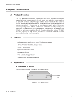
Redundant Power Supply ■■ Apearance of RPS2 The appearance of RPS2 is shown as the following figure. RPS Slot FFFFFFFFFFF Appearance of RPS2 RPS Slot To install RPS150 into RPS2, please insert RPS150 into the RPS Slot. Each RPS2 is designed to hold up to 2 RPS150. For detail instructions, please refer to 2.4 Product Installation. 03 Introduction
-
 1
1 -
2
-
 3
3 -
 4
4 -
 5
5 -
 6
6 -
 7
7 -
 8
8 -
 9
9 -
 10
10 -
 11
11 -
 12
12 -
 13
13 -
14
-
15
-
16
-
17
-
18
-
19
-
20
 |
 |

03
Redundant Power Supply
Introduction
Apearance of RPS2
■
The appearance of RPS2 is shown as the following figure.
RPS Slot
Appearance of RPS2
Figure 1-3
RPS Slot
To install RPS150 into RPS2, please insert RPS150 into the RPS Slot. Each RPS2
is designed to hold up to 2 RPS150. For detail instructions, please refer to
2.4
Product Installation
.