TP-Link RPS150 RPS150 V1 IG - Page 7
Rear Panel of RPS150
 |
View all TP-Link RPS150 manuals
Add to My Manuals
Save this manual to your list of manuals |
Page 7 highlights
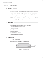
Redundant Power Supply Indicators You can monitor the running status of RPS150 through the Power and FAN LEDs. LED Power FAN Status On Flashing Off On Flashing Off Indication The system power supply is normal The system power supply is abnormal The system power supply is off or abnormal The fan works normally The fan works abnormally The power supply is off or the fan works abnormally ■■ Rear Panel of RPS150 The rear panel of RPS150 is shown as the following figure. FFFFFFFFFFF Rear Panel of RPS150 AC Power Input Grounding Terminal Protective Cover AC Power Input On the right side of the rear panel, and the input AC power should be 100-240V~ 50/60Hz. Grounding Terminal On the left side of the AC Power Input, please ground the device with the provided Ground Cable. You can also ground the device through the PE (Protecting Earth) cable of AC cord. For detailed information, please refer to section 3.1 Connect to Ground. Protective Cover It is used to protect the DC Power Output Socket. Remove it to connect RPS150 to the powered device. Caution: ■■ Please use the provided power cord and verify the power supply is 100-240V~50/60Hz. ■■ The electrical outlet shall be installed near the device and shall be easily accessible. Introduction 02
-
 1
1 -
 2
2 -
 3
3 -
 4
4 -
 5
5 -
 6
6 -
 7
7 -
 8
8 -
 9
9 -
 10
10 -
 11
11 -
 12
12 -
13
-
14
-
15
-
16
-
17
-
18
-
19
-
20
 |
 |
