Thermador HMWN30FS Installation Instructions - Page 10
For both ins tallation, method
 |
View all Thermador HMWN30FS manuals
Add to My Manuals
Save this manual to your list of manuals |
Page 10 highlights
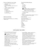
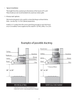
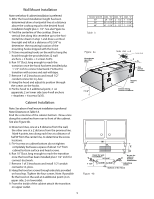
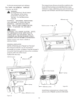
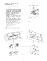
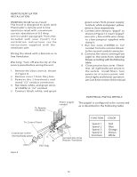
Fix Duct to transitionand seal withtape. For both ins tallation method : 10. Wiring the HOOD: WARNING: To Avoid Electrical Shock Hazard Turn off power at the service panel before wiring this unit. 120 VAC, 15 or 20 Amp circuit required. ELECTRICAL GROUNDING INSTRUCTIONS THIS APPLIANCE IS FITTED WITH AN ELECTRICAL JUNCTION BOX WITH 3 WIRES, ONE OF WHICH (GREEN/YELLOW) SERVES TO GROUND THE APPLIANCE. WARNING: TO PROTECT YOU AGAINST ELECTRIC SHOCK, THE GREENAND YELLOW WIRE MUST BE CONNECTEDTO THE GROUNDING WIRE IN YOURHOME ELECTRICALSYSTEM,AND IT MUST UNDERNO CIRCUNSTANCEBSECUTORREMOVED. Failure to do so can result in death or electrical shock. INTEGRAL VENTILATOR INSTALLATION Models VTN600F & VTN1000F The Integral ventilator can be mounted to discharge air as show on figure 3 and 4b at page 9. It must be fixed through the slots of the ventilator and pins with nuts of the hood. Tighten the two nuts. Machine screws Millimetric nuts The integral motor blowers should be installed to the hood with the hardware provided (Machine screws, millimetric screws, millimetric nuts, motor bracket and spring) in the VTN600F and VTN1000F hardware bags. Machine screws Millimetric nuts Motor Bracket Spring Figure 5a Motor Bracket Spring Millimetric screws Millimetric screws Figure 5b Install these components as is shown in the picture 5a for VTN600F and 5b for VTN1000F. 10
-
 1
1 -
2
-
3
-
4
-
 5
5 -
 6
6 -
 7
7 -
 8
8 -
 9
9 -
 10
10 -
 11
11 -
 12
12 -
 13
13 -
 14
14 -
 15
15 -
16
-
17
-
18
-
19
-
20
-
21
-
22
-
23
-
24
-
25
-
26
-
27
-
28
-
29
-
30
-
31
-
32
-
33
-
34
-
35
 |
 |
