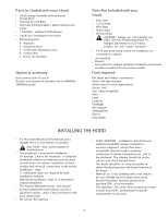
Thermador HMWN30FS Installation Instructions - Page 7
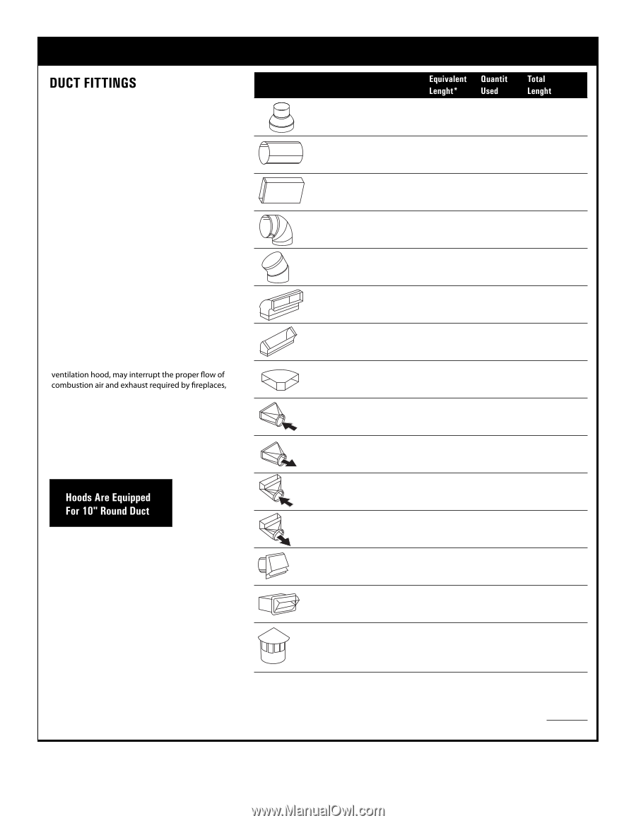
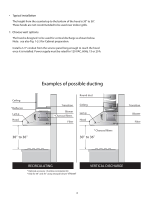
Table 1. Ventilator performance calculation
 |
View all Thermador HMWN30FS manuals
Add to My Manuals
Save this manual to your list of manuals |
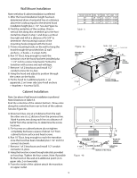
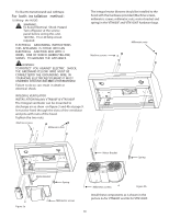
Page 7 highlights
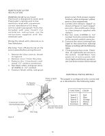
Table 1. Ventilator performance calculation Duct Piece Us e this chart to compute maximum permissable lengths for duct runs to outdoors . Note: Do not exceed maximum permissable equivalent lengths! Maximum recommended duct length for these hoods: 150 feet Fl exible ducting: If flexible metal ducting is used, all the equivalent feet values in the table should be doubled. The flexible metal duct should be straight and smooth and extended as much as possible. Do NOT use flexible plastic ducting. Note: Any home ventilation system, such as a gas furnaces, gas water heaters and other naturally vented systems. To minimize the chance of interruption of such naturally vented systems, follow the heating equipment manufacturer's guidelines and safety standards such as those published by NFPA and ASHRAE. *Hoods are supplied with a 10" round transition. A locally supplied transition is required for other sizes. Note: Outlet on top of hood is 8-1/8" x 8". 10" round to 8" roun d Round , straight 3-1/4" x 10" 3-1/4" x 12 " straight 90° elbow 5 ft. 1 ft. (per foot length ) 1 ft. (p er f oot length) 8" Di a. 17 ft. 10" Dia. 24 ft . 45° elbow 8" Di a. 10 ft. 10" Dia. 14 ft . 3 -1⁄4" x 12" 3-1/4" x 10" 90° elbow 3-1/4" x 10 " 3-1/4" x 12 " 45° elbow 3-1/4" x 10" 3-1/4" x 12" 90° flat elbow 10"round transition to 3-1/4" x 10" or 3-1/ 4" x 12" 3-1/4" x 10" or 3-1/4" x 12" to 10" round transiti on 10" round to 3-1/4" x 10" 3-1/4" x 12" transition 90° elbow 3-1/4" x 10 " 3-1/4" x 12" t o 10" round transiti on 90° elbow Roun d wall c ap with damper 3-1/4" x 10" 3-1/4" x 12" wall cap with damper 15 ft. 14 ft. 8 ft. 9 ft. 33 ft. 36 ft. 9 ft. 6 ft. 16 ft. 13 ft. 9 ft. 8 ft. 8" Dia. 32 ft. 10" Dia. 41 ft. 24 ft. 26 ft. Round roof cap 8" Dia. 44 ft. 10" Di a. 56 ft . Total Duct Run 7
-
 1
1 -
 2
2 -
 3
3 -
 4
4 -
 5
5 -
 6
6 -
 7
7 -
 8
8 -
 9
9 -
 10
10 -
 11
11 -
 12
12 -
13
-
14
-
15
-
16
-
17
-
18
-
19
-
20
-
21
-
22
-
23
-
24
-
25
-
26
-
27
-
28
-
29
-
30
-
31
-
32
-
33
-
34
-
35
 |
 |