Toshiba TS605 Service Manual - Page 68
Cpu Memory, 2.3 Real Time Clock Rtc, 2.4 Lcd Module, 2.5 Camera And Backend Ic - drivers
 |
View all Toshiba TS605 manuals
Add to My Manuals
Save this manual to your list of manuals |
Page 68 highlights
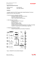
MOBILE COMMUNICATIONS DIVISION CUSTOMER SERVICES 6.2.2 CPU MEMORY To reduce component space, the phone uses a BGA package with Dual operation Flash memory and SRAM MCP. The following memory configuration is used: 256Mbits Flash memory organized as 16M * 16bits 64Mbits Pseudo RAM organized as 4M * 16 bits 6.2.3 REAL TIME CLOCK (RTC) Real Time Clock function is provided by a RTC block module embedded in AD6527B. The module is synchronized to an external 32.768 kHz crystal and has a backup power source using an external RTC battery. AD6527B also provide clock auto compensation function if clock frequency drifts with temperature change, frequency drift can be compensated by writing compensation registers. This functionality allows the application software to implement standard, calendar, or organizer functions such as: Time and date display Programmable alarm Programmable mobile activation The RTC interrupt is routed through the IRQ-controller to the MCU or the DSP, as defined by software in interrupt configuration registers. 6.2.4 LCD MODULE The LCD module (panel: 176*220, TFT), white LED backlight module and driver chip. Driver chip is connected to the main PCB via a flexible PCB strip. The LCD driver is controlled by setting the command register from the AD6527 u-wire interface, signals then bypassed through camera backend IC (AIT811) to LCD driver. An I/O line (H_LCD_A0) is used to distinguish transferring command or data. 6.2.5 CAMERA AND BACKEND IC A powerful camera backend IC (AIT811) is used for camera signal processing, the on-chip processor implements versatile features of digital still camera like AE (Auto Exposure), AWB (Auto White Balance), digital room and some image special effects. The maximum supported resolution is VGA (640*480). AIT811 also contains many features, which are suitable for mobile phone camera applications including hardware JPEG coding/encoding, 2D graphic engine and hardware color DSP. The camera module is consisted by lens, CMOS sensor, mechanical hosing and a flexible PCB strip. The maximum resolution of CMOS sensor is also 640*480. Version 1.0 22/11/2006 Created by Konrad Szombara Page 68 of 103
-
 1
1 -
2
-
3
-
4
-
5
-
6
-
7
-
8
-
9
-
10
-
11
-
12
-
13
-
14
-
15
-
16
-
17
-
18
-
19
-
20
-
21
-
22
-
23
-
24
-
25
-
26
-
27
-
28
-
29
-
30
-
31
-
32
-
33
-
34
-
35
-
36
-
37
-
38
-
39
-
40
-
41
-
42
-
43
-
44
-
45
-
46
-
47
-
48
-
49
-
50
-
51
-
52
-
53
-
54
-
55
-
56
-
57
-
58
-
59
-
60
-
61
-
62
-
 63
63 -
 64
64 -
 65
65 -
 66
66 -
 67
67 -
 68
68 -
 69
69 -
 70
70 -
 71
71 -
 72
72 -
 73
73 -
74
-
75
-
76
-
77
-
78
-
79
-
80
-
81
-
82
-
83
-
84
-
85
-
86
-
87
-
88
-
89
-
90
-
91
-
92
-
93
-
94
-
95
-
96
-
97
-
98
-
99
-
100
-
101
-
102
-
103
 |
 |
