Weider 3130 English Manual - Page 19
Pulley 48. Attach the Pulley, a Cable Trap 56
 |
View all Weider 3130 manuals
Add to My Manuals
Save this manual to your list of manuals |
Page 19 highlights
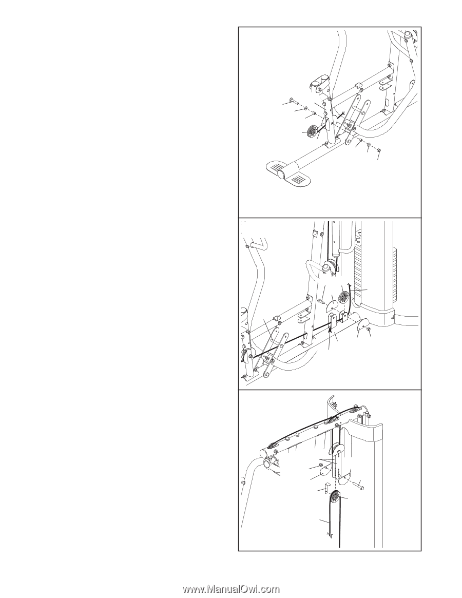
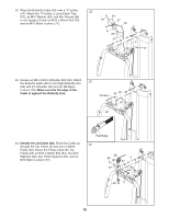
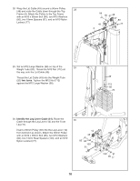
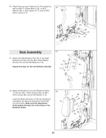
31. Attach a 90mm Pulley (48) to the Front Leg (10) 31 with an M10 x 65mm Bolt (85), two M10 Washers (80), two 13mm Steel Spacers (109), and an M10 Nylon Locknut (77). Make sure the Leg Lever Cable (51) is under the Pulley. 10 85 80 109 48 51 109 80 77 32. Route the Leg Lever Cable (51) under the 32 89.5mm Spacer (59), through the Upright (2), and under the indicated rod in the Base (1). Wrap the Leg Lever Cable around a 90mm Pulley (48). Attach the Pulley to the Base with an M10 x 45mm Bolt (86), two Half Guards (55), and an M10 Nylon Locknut (77). 59 86 48 55 51 1 55 77 Rod 33. Wrap the Leg Lever Cable (51) over a 90mm 33 Pulley (48). Attach the Pulley, a Cable Trap (56), and two Half Guards (55) to the second hole from the bottom of the Pulley Plates (60) with an M10 x 50mm Bolt (97) and an M10 Nylon Locknut (77). Make sure the Cable Trap and the Half Guards are oriented as shown. 60 77 55 56 51 55 97 48 19
-
 1
1 -
2
-
3
-
4
-
5
-
6
-
7
-
8
-
9
-
10
-
11
-
12
-
13
-
 14
14 -
 15
15 -
 16
16 -
 17
17 -
 18
18 -
 19
19 -
 20
20 -
 21
21 -
 22
22 -
 23
23 -
 24
24 -
25
-
26
-
27
-
28
-
29
-
30
-
31
-
32
-
33
-
34
-
35
-
36
 |
 |