Weider 3130 English Manual - Page 27
Weight Resistance Chart
 |
View all Weider 3130 manuals
Add to My Manuals
Save this manual to your list of manuals |
Page 27 highlights
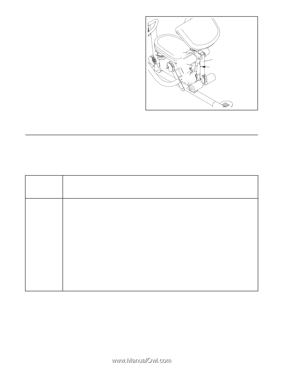
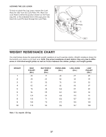
LOCKING THE LEG LEVER To lock or unlock the Leg Lever, remove the Lock Plate Pin (95) from the Lock Plate (14). Move the Lock Plate to either the position shown on the Front Leg (10), or the indicated hole in the Leg Lever (12). Insert the Lock Pin back through the Lock Plate. 10 14 95 12 Hole WEIGHT RESISTANCE CHART The chart below shows the approximate weight resistance at each exercise station. Weight resistance shown for the butterfly arm station is for each arm. Note: The actual resistance at each station may vary due to differences in individual weight plates as well as friction between the cables, pulleys, and weight guides. WEIGHT 1 2 3 4 5 6 7 8 9 10 HIGH PULLEY (lbs.) 26 38 51 62 76 94 124 133 165 178 BUTTERFLY ARM (lbs.) 17 24 32 41 48 55 64 71 79 90 PRESS ARM (lbs.) 46 63 76 90 104 121 138 153 172 195 LEG LEVER (lbs.) 27 42 54 69 87 103 116 127 135 167 LOW PULLEY (lbs.) 25 39 52 67 80 92 111 121 140 168 Note: 1 lb. equals .454 kg. 27
-
 1
1 -
2
-
3
-
4
-
5
-
6
-
7
-
8
-
9
-
10
-
11
-
12
-
13
-
14
-
15
-
16
-
17
-
18
-
19
-
20
-
21
-
 22
22 -
 23
23 -
 24
24 -
 25
25 -
 26
26 -
 27
27 -
 28
28 -
 29
29 -
 30
30 -
 31
31 -
 32
32 -
33
-
34
-
35
-
36
 |
 |