Weider E2000 English Manual - Page 10
Cable Assembly
 |
View all Weider E2000 manuals
Add to My Manuals
Save this manual to your list of manuals |
Page 10 highlights
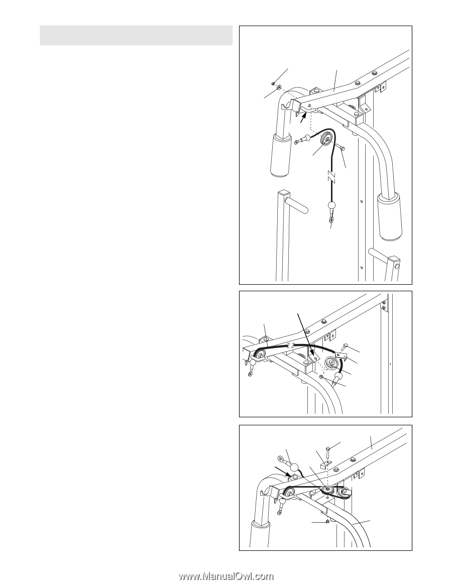
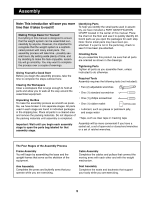
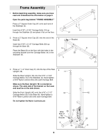
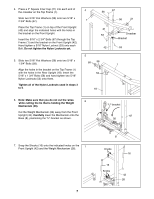
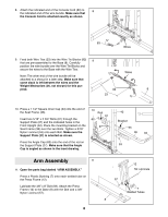
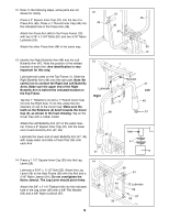
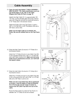
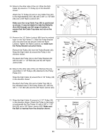
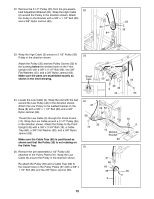
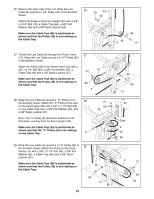
Cable Assembly 15 15. Open the parts bag labeled ÒCABLE ASSEMBLY AND PULLEYS.Ó For Cable identification and routing during steps 15Ð30, refer to the Cable Diagram and Cable ID Chart on page 19. Identify the High Cable (2). It is approximately 163 55 1/2Ó long. It is the shortest cable and it has a ball on each end. Wrap the end with the small ball around a 3 1/2Ó Pulley (35) in the direction shown. Attach the Pulley (35) to the Top Frame (1) with a 3/8Ó x 3 1/2Ó Bolt (54), a 3/8Ó Flat Washer (55) and a 3/8Ó Nylon Jamnut (63). Make sure the High Cable (2) is between the Pulley (35) and the welded hook on the Top Frame (1). 63 1 Hook 35 54 2 16. Wrap the High Cable (2) around a ÒVÓ-Pulley (6) in the direction shown. Attach the ÒVÓ-Pulley (6) and a Long Cable Trap (50) to the indicated bracket with a 3/8Ó x 2 1/4Ó Bolt (65) and a 3/8Ó Nylon Locknut (57). Make sure the Long Cable Trap is positioned as shown, so it will hold the Cable in place. 16 2 Welded Bracket 65 50 6 57 17. Wrap the High Cable (2) around a ÒVÓ-Pulley (6) in the direction shown. Attach the ÒVÓ-Pulley (6) and a Long Cable Trap (50) to the Left Butterfly Arm (47) with a 3/8Ó x 2 1/2Ó Bolt (96) and a 3/8Ó Nylon Locknut (57). Make sure the Long Cable Trap (50) is positioned as shown. It may be helpful to take the Butterfly Arm (47) through one full range of motion to ensure that the Cable Trap does not rub on the cable. Route the High Cable (2) under the Top Frame (1) between the ÒVÓ-Pulley (6) and the crossbar. 10 17 2 Crossbar 50 6 57 1 96 47
-
 1
1 -
2
-
3
-
4
-
 5
5 -
 6
6 -
 7
7 -
 8
8 -
 9
9 -
 10
10 -
 11
11 -
 12
12 -
 13
13 -
 14
14 -
 15
15 -
16
-
17
-
18
-
19
-
20
-
21
-
22
-
23
-
24
-
25
-
26
-
27
-
28
 |
 |