Weider E2000 English Manual - Page 8
Arm Assembly
 |
View all Weider E2000 manuals
Add to My Manuals
Save this manual to your list of manuals |
Page 8 highlights
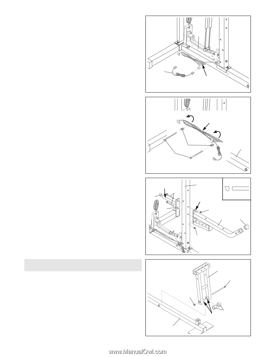
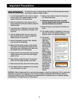
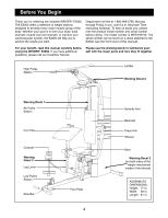
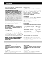
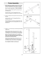
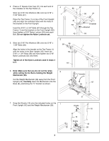
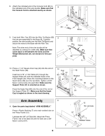
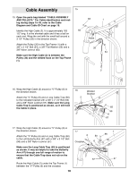
8. Attach the indicated end of the Console Cord (83) to 8 the indicated end of the wire bundle. Make sure that the Console Cord is attached exactly as shown. 26 83 Wires 9. Feed both Wire Ties (23) into the Wire Tie Blocks (82) 9 that are pre-assembled to the Base (8). Carefully position the wire bundle over the Wire Tie Blocks and secure the wires to the Base with the Wire Ties. Note: The other end of the wire bundle will be attached to a shroud in a later step. Make sure that some slack is left between the wires and the Weight Mechanism (26, not shown) for this purpose. Wires 82 8 23 10. Press a 1 1/2Ó Square Inner Cap (33) into the end of the Seat Frame (36). Insert two 5/16Ó x 2 3/4Ó Bolts (67) through the Support Plate (27) and the indicated holes in the Front Upright (42). Place the mounting bracket on the Seat Frame (36) over the two Bolts. Tighten a 5/16Ó Nylon Locknut (53) onto each Bolt. Make sure the Support Plate (27) is oriented as shown. Press the Angle Cap (62) onto the end of the rod on the Support Plate (27). Make sure that the Angle Cap is angled as shown in the inset drawing. 10 Rod 67 62 27 42 Bracket 53 36 33 53 Arm Assembly 11 11. Open the parts bag labeled ÒARM ASSEMBLY.Ó Press a Plastic Bushing (7) onto each welded tube on the Press Frame (12). Lubricate the 3/8Ó x 8Ó Bolt (59). Attach the Press Frame (12) to the Base (8) with the Bolt and a 3/8Ó Nylon Locknut (57). 8 57 8 12 59 Lubricate 7 Welded Tubes
-
 1
1 -
2
-
 3
3 -
 4
4 -
 5
5 -
 6
6 -
 7
7 -
 8
8 -
 9
9 -
 10
10 -
 11
11 -
 12
12 -
 13
13 -
14
-
15
-
16
-
17
-
18
-
19
-
20
-
21
-
22
-
23
-
24
-
25
-
26
-
27
-
28
 |
 |