Weider Max By Xp400 English Manual
Weider Max By Xp400 Manual
 |
View all Weider Max By Xp400 manuals
Add to My Manuals
Save this manual to your list of manuals |
Weider Max By Xp400 manual content summary:
- Weider Max By Xp400 | English Manual - Page 1
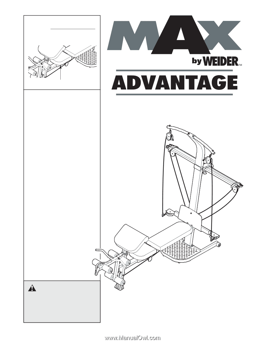
reference. Serial Number Decal (under seat) • Assembly • Adjustments • Part List and Drawing WEIGHT SYSTEM EXERCISER User's Manual CAUTION Read all precautions and instructions in this manual before using this equipment. Save this manual for future reference. Sears, Roebuck and Co., Hoffman - Weider Max By Xp400 | English Manual - Page 2
13 CABLE DIAGRAM 17 EXERCISE GUIDELINES 18 ORDERING REPLACEMENT PARTS Back Cover FULL ONE-YEAR WARRANTY Back Cover Note: A PART IDENTIFICATION CHART and a PART LIST/EXPLODED DRAWING are attached in the center of this manual. Remove the PART IDENTIFICATION CHART and PART LIST/EXPLODED DRAWING - Weider Max By Xp400 | English Manual - Page 3
and feet away from moving parts. 9. Always wear athletic shoes for foot protection while exercising. 10. The top frame is not designed to be used for pull-up exercises. Do not hang on the top frame. 11. The resistance system is designed to support a maximum user weight of 300 pounds. 12. Always - Weider Max By Xp400 | English Manual - Page 4
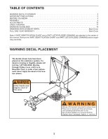
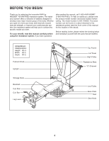
you for selecting the innovative MAX by WEIDER™ ADVANTAGE resistance system. The resistance system offers a selection of stations system (see the front cover of this manual for the location of the decal). Before reading further, please review the drawing below and familiarize yourself with the parts - Weider Max By Xp400 | English Manual - Page 5
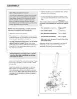
may have been pre-attached for shipping. If a part is not in the parts bag, check to see if it has been pre-attached. • Tighten all parts as you assemble them, unless instructed to do otherwise. • As you assemble the resistance system, make sure all parts are oriented as shown in the drawings. The - Weider Max By Xp400 | English Manual - Page 6
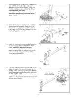
2. Attach a Wheel (31) to the outside of the Base (1) with an M10 x 78mm Bolt (81), three M10 2 Washers (75), and an M10 Nylon Locknut (76). Do not overtighten the Locknut; the Wheel must be able to turn easily. Attach the other Wheel (not shown) in the same manner. 3. Orient the Cross Tube ( - Weider Max By Xp400 | English Manual - Page 7
6. Attach the Lat Tower (4) to the Upright (3) with 6 four M10 x 25mm Button Screws (87), and four M10 Lock Washers (103). Attach the Name Plate (89) to the Lat Tower (4) 4 with two M4 x 16mm Screws (62). 62 89 62 103 87 87 103 3 7. Attach two Eyebolts (34) to the Top Frame (10) with two M8 - Weider Max By Xp400 | English Manual - Page 8
) to one end of the Seat Carriage (12) with an M8 x 104mm Bolt (60) and an M8 Nylon Locknut (65) as shown. Make sure the parts are oriented as shown in the inset drawing; the Seat Knob (not shown) will not engage the Bench Rail (not shown) if they are incorrectly - Weider Max By Xp400 | English Manual - Page 9
12. Attach a Plastic Foot (53) to the Backrest Frame (15) with an M4 x 16mm Screw (62). 12 Attach the two Guard Plates (17) to the inside of the Backrest Frame (15) with four M4 x 16mm Screws (62). 15 53 62 13. Attach the Backrest (14) to the Backrest Frame (15) with four 1/4" x 45mm Screws (58 - Weider Max By Xp400 | English Manual - Page 10
16. Locate the Fulcrum (18) on the Lat Tower (4) (see the inset drawing). Slide the Tray (35) onto the rods on the Fulcrum. Make sure the Tray is oriented as shown in the drawing. Set the resistance bars into the Tray (35) in the following order: the 10-pound Removable Resistance Bar (67), the 20- - Weider Max By Xp400 | English Manual - Page 11
20. Wrap the Long Cable (80) under a 90mm Pulley (28) as shown. Attach the Pulley, a Cable Trap (29), an M10 Washer (75), and two Finger Guards (110) to the Upright (3) with an M10 x 127mm Button Bolt (56) and an M10 Nylon Locknut (76). Note: The Bolt will be packaged separately for identification. - Weider Max By Xp400 | English Manual - Page 12
use of the remaining parts will be explained in ADJUSTMENTS, beginning on the following page. Before using the resistance system, pull the long cable a few times to be sure that it moves smoothly over the pulleys. If the cable does not move smoothly, find and correct the problem. IMPORTANT: If the - Weider Max By Xp400 | English Manual - Page 13
the most benefit from your exercise program. Also, refer to the accompanying exercise guide to see the correct form for each exercise. Make sure all parts are properly tightened each time you use the resistance system. Replace worn parts immediately. The resistance system can be cleaned with a damp - Weider Max By Xp400 | English Manual - Page 14
, the resistance will increase rapidly. Additional resistance can be added to the resistance system by calling toll-free 1-877-992-5999 and asking for model number WEMC0642 (100-pound MAX PACK) or WEMC0942 (200-pound MAX PACK). 33 51 49 80 "U"-Channel 67 Resistance Bars 35 36 44 "U"-Channel - Weider Max By Xp400 | English Manual - Page 15
the Bench Rail (5). Rest the Backrest against the Upright (3). For row exercises, remove the Backrest (14). Hold the Backrest vertically over the Seat Carriage (12) (see the inset drawing). STORING THE RESISTANCE SYSTEM To store the resistance system, remove the Leg Lever (not shown) (see ATTACHING - Weider Max By Xp400 | English Manual - Page 16
USING THE REMOVABLE RESISTANCE BARS The Removable Resistance Bars (36, 67) can be used to exercise apart from the resistance system, as shown in the video or on the exercise guide. To remove a Resistance Bar, pull it out of the Tray (35). 67 36 To replace the Removable Resistance Bars (36, 67), - Weider Max By Xp400 | English Manual - Page 17
Cable (80). Use the diagram to make sure that the cable has been assembled correctly. If the cable has not been correctly routed, the resistance system will not function properly and damage may occur. The 5 numbers show the correct route for the cable. Long Cable (80) 7 6 4 3 2 1 17 - Weider Max By Xp400 | English Manual - Page 18
Weight Loss To lose weight, use a low amount of resistance and increase the number of repetitions in each set. Exercise exercise, and moving only the appropriate parts of the body. Exercising in an uncontrolled manner will leave you feeling exhausted. On the exercise guide accompanying this manual - Weider Max By Xp400 | English Manual - Page 19
of sets and repetitions completed. Record your weight and key body measurements at the end of every month. Remember, the key to achieving the greatest results is to make exercise a regular and enjoyable part of your everyday life. A B C D E F G H I J K L M N O P Q R S T U V W X MUSCLE CHART - Weider Max By Xp400 | English Manual - Page 20
each drawing is the key number of the part, from the PART LIST on the reverse side of this page. Note: Some small parts may have been pre-attached. If a part is not in the parts bag, check to see if it has been pre-attached. If a part is missing, call toll-free 1-877-992-5999 - Weider Max By Xp400 | English Manual - Page 21
1/4" x 45mm Bolt (58) M10 x 65mm Button Screw (70) M10 x 66mm Carriage Bolt (83) M10 x 72mm Bolt (64) M10 x 78mm Bolt (81) M10 x 91mm Bolt (90) M10 x 103mm Bolt (66) M8 x 104mm Bolt (60) M8 x 114mm Rod (57) M10 x 127mm Button Bolt (56) M10 x 128mm Button Bolt (24) M10 x 147mm Carriage Bolt (73) - Weider Max By Xp400 | English Manual - Page 22
Cap Leg Lever Bushing Long Pin Cotter Pin Short Pin Finger Guard 19mm Round Inner Cap Long Handle User's Manual Exercise Guide Exercise Decal Allen Wrench Allen Wrench Note: "#" indicates a non-illustrated part. Specifications are subject to change without notice. See the back cover of the user - Weider Max By Xp400 | English Manual - Page 23
EXPLODED DRAWING-Model No. 831.15392.3 R1005A 65 75 59 70 85 79 38 93 100 34 10 21 71 76 85 20 65 100 95 77 40 59 28 38 82 34 33 85 21 85 88 44 36 14 71 16 76 101 28 4 67 33 86 72 96 79 100 85 85 20 53 62 15 62 58 62 58 103 87 35 18 85 88 91 37 84 76 101 - Weider Max By Xp400 | English Manual - Page 24
occurs due to defect in material or workmanship in this RESISTANCE SYSTEM EXERCISER, contact the nearest Sears Service Center throughout the United States and Sears will repair or replace the RESISTANCE SYSTEM EXERCISER, free of charge. Parts will be replaced for five years. The resistance bar will
-
 1
1 -
 2
2 -
 3
3 -
 4
4 -
 5
5 -
 6
6 -
 7
7 -
8
-
9
-
10
-
11
-
12
-
13
-
14
-
15
-
16
-
17
-
18
-
19
-
20
-
21
-
22
-
23
-
24
 |
 |
CAUTION
Read all precautions and instruc-
tions in this manual before
using this equipment. Save this
manual for future reference.
Model No. 831.15392.3
Serial No.
Write the serial number in the
space above for future reference.
Serial Number Decal (under seat)
WEIGHT SYSTEM EXERCISER
User’s Manual
• Assembly
• Adjustments
• Part List and Drawing
Sears, Roebuck and Co., Hoffman Estates, IL 60179