Weider Max By Xp400 English Manual - Page 9
Attach a Plastic Foot 53 to the Backrest Frame
 |
View all Weider Max By Xp400 manuals
Add to My Manuals
Save this manual to your list of manuals |
Page 9 highlights
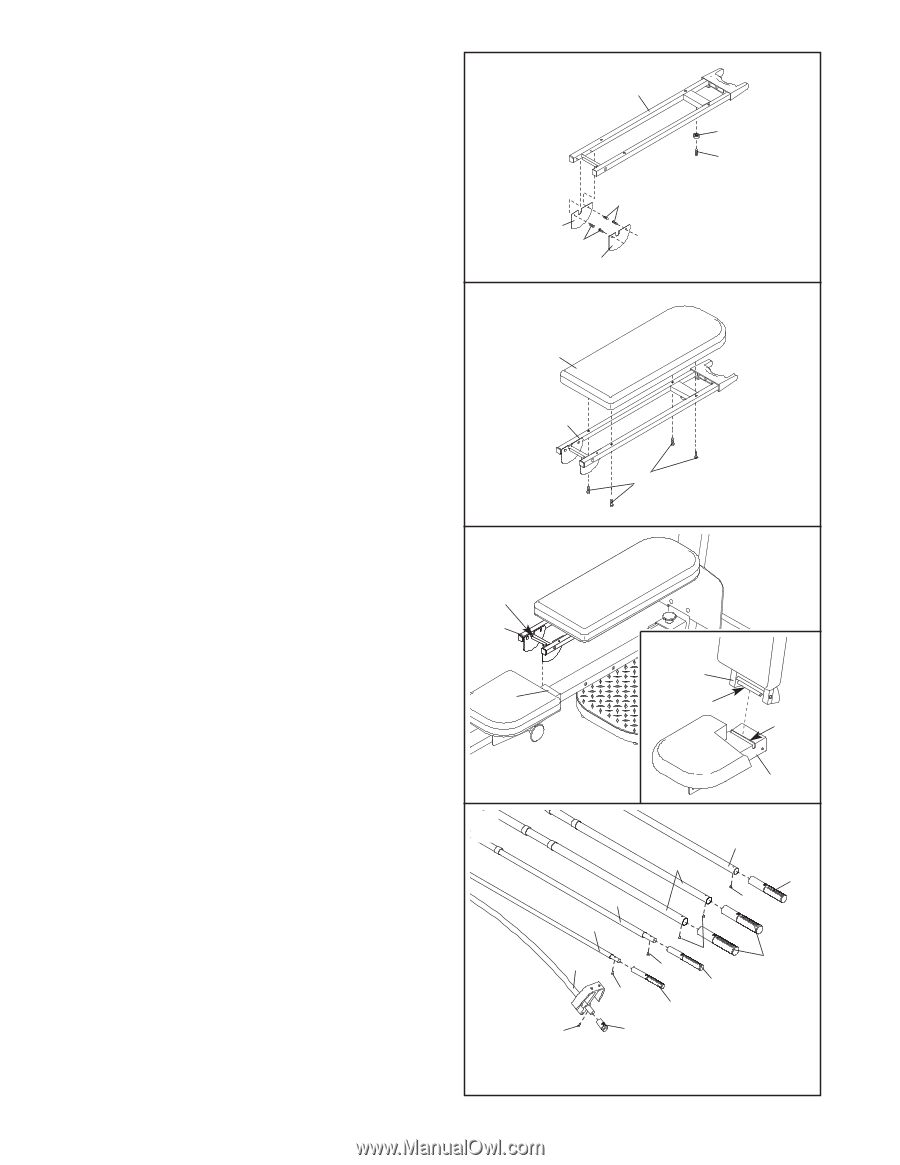
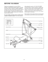
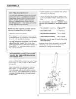
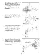
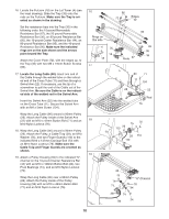
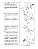
12. Attach a Plastic Foot (53) to the Backrest Frame (15) with an M4 x 16mm Screw (62). 12 Attach the two Guard Plates (17) to the inside of the Backrest Frame (15) with four M4 x 16mm Screws (62). 15 53 62 13. Attach the Backrest (14) to the Backrest Frame (15) with four 1/4" x 45mm Screws (58). 62 17 62 17 13 14 15 14. Insert the rod on the Backrest Frame (15) into the slot in the Seat Carriage (12). Hold the Backrest Frame vertically over the Seat Carriage and slide the rod into the slot, as shown in the inset drawing. 14 Rod 15 12 58 15 Rod Slot 15. Attach the two 10-pound Short Resistance Bar 15 Caps (20) to the 10-pound Center Resistance Bar (44) with two M4 x 12mm Flat Head Screws (85). Attach the two 10-pound Resistance Bar Caps (101) to the 10-pound Removable Resistance Bar (67), the two 20-pound Resistance Bar Caps (88) to the 20-pound Removable Resistance Bar (36), the four 80-pound Resistance Bar Caps (100) to the two 80-pound Resistance Bars (95), and the two 40-pound Resistance Bar Caps (79) to the 40-pound Resistance Bar (96) with ten M4 x 12mm Flat Head Screws (85). 12 36 67 96 95 79 85 44 85 100 85 88 85 101 85 20 9
-
 1
1 -
2
-
3
-
 4
4 -
 5
5 -
 6
6 -
 7
7 -
 8
8 -
 9
9 -
 10
10 -
 11
11 -
 12
12 -
 13
13 -
 14
14 -
15
-
16
-
17
-
18
-
19
-
20
-
21
-
22
-
23
-
24
 |
 |