Weider Max By Xp400 English Manual - Page 11
Attach the Pulley, a Cable Trap 29, an M10
 |
View all Weider Max By Xp400 manuals
Add to My Manuals
Save this manual to your list of manuals |
Page 11 highlights
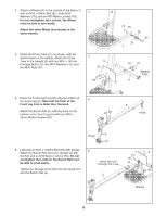
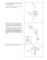
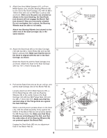
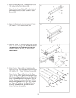
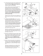
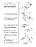
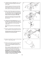
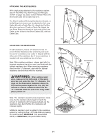
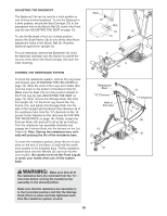
20. Wrap the Long Cable (80) under a 90mm Pulley (28) as shown. Attach the Pulley, a Cable Trap (29), an M10 Washer (75), and two Finger Guards (110) to the Upright (3) with an M10 x 127mm Button Bolt (56) and an M10 Nylon Locknut (76). Note: The Bolt will be packaged separately for identification. Make sure the Cable Trap and Finger Guards are oriented as shown. 20 3 56 75 28 110 76 110 80 29 21. Attach a Pulley Housing (94) to the indicated "U"channel on the 10-pound Center Resistance Bar (44) with an M10 x 128mm Button Bolt (24), two Pivot Bushings (74), and an M10 Nylon Locknut (76). Wrap the Long Cable (80) over a 90mm Pulley (28). Attach the Pulley inside of the Pulley Housing (94) with an M10 x 42mm Button Bolt (71) and an M10 Nylon Locknut (76). 22. Wrap the Long Cable (80) around a 90mm Pulley (28). Attach the Pulley, a Cable Trap (29), an M10 Washer (75), and two Finger Guards (110) to the indicated M10 x 147mm Carriage Bolt (73) with an M10 Nylon Locknut (76). Make sure the Cable Trap and Finger Guards are oriented as shown. 21 44 74 24 94 71 74 76 76 28 80 22 80 76 28 110 110 29 75 23. Make sure there are no resistance bars under the 73 "U"-channels on the 10-pound Center Resistance Bar (not shown). Have a second person pull on the Long Cable (80) to create slack in the Cable. 23 Insert the end of the Long Cable (80) through the welded tube on the indicated end of the Cross Tube (11) and then through the remaining Swivel Arm (22). Make sure the Cable is on the indicated side of the welded rod in the Swivel Arm. 71 104 Rod 80 Insert the Swivel Arm (22) into the welded tube on the Cross Tube (11). Secure the Swivel Arm with an M4 x 5mm Screw (104). 22 28 76 11 Wrap the Long Cable (80) around a 90mm Pulley (28). Attach the Pulley inside of the Swivel Arm (22) with an M10 x 42mm Button Bolt (71) and an M10 Nylon Locknut (76). 11
-
 1
1 -
2
-
3
-
4
-
5
-
 6
6 -
 7
7 -
 8
8 -
 9
9 -
 10
10 -
 11
11 -
 12
12 -
 13
13 -
 14
14 -
 15
15 -
 16
16 -
17
-
18
-
19
-
20
-
21
-
22
-
23
-
24
 |
 |
