Weider Max By Xp400 English Manual - Page 7
Attach the Leg Lever 7 to the Front Leg 6
 |
View all Weider Max By Xp400 manuals
Add to My Manuals
Save this manual to your list of manuals |
Page 7 highlights
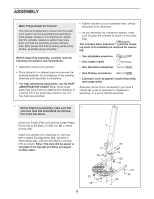
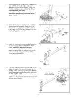
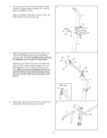
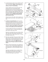
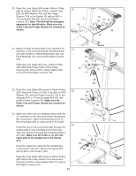
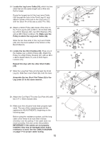
6. Attach the Lat Tower (4) to the Upright (3) with 6 four M10 x 25mm Button Screws (87), and four M10 Lock Washers (103). Attach the Name Plate (89) to the Lat Tower (4) 4 with two M4 x 16mm Screws (62). 62 89 62 103 87 87 103 3 7. Attach two Eyebolts (34) to the Top Frame (10) with two M8 Washers (59) and two M8 Nylon Locknuts (65). Do not overtighten the Locknuts; the Eyebolts must be able to rotate freely. Attach the Top Frame (10) to the Lat Tower (4) with two M10 x 65mm Button Screws (70), two M10 Washers (75), and the Top Frame Cover (93). Make sure that the Eyebolts (34) are oriented as shown in the inset drawing. If they are not, turn the Top Frame around and reattach it. 7 65 59 70 75 93 10 34 65 59 Side View 10 4 34 4 8. Attach the Leg Lever (7) to the Front Leg (6) with a Long Pin (107) and a Cotter Pin (108). 34 8 107 6 7 108 7
-
 1
1 -
 2
2 -
 3
3 -
 4
4 -
 5
5 -
 6
6 -
 7
7 -
 8
8 -
 9
9 -
 10
10 -
 11
11 -
 12
12 -
13
-
14
-
15
-
16
-
17
-
18
-
19
-
20
-
21
-
22
-
23
-
24
 |
 |
