Weider Max By Xp400 English Manual - Page 12
Pulley is above the Leg Lever Cable 32.
 |
View all Weider Max By Xp400 manuals
Add to My Manuals
Save this manual to your list of manuals |
Page 12 highlights
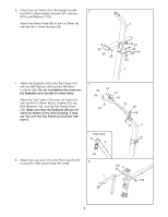
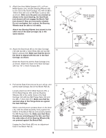
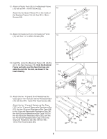
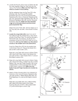
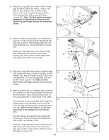
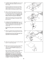
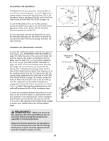
24. Locate the Leg Lever Cable (32), which has two 24 ends that are the same length and a third end that is longer. Route the longest end of the Leg Lever Cable (32) through the hole in the Front Leg (6), and attach it inside of the hole in the Leg Lever (7) with the Short Pin (109) and a cotter Pin (108). 25. Attach a 90mm Pulley (28) inside of the hole in 25 the Front Leg (6) with an M10 x 91mm Bolt (90), two 26mm Spacers (52), two M10 Washers (75), and an M10 Nylon Locknut (76). Make sure the Pulley is above the Leg Lever Cable (32). Slide the two free ends of the Leg Lever Cable (32) onto the hook welded to the bottom of the Bench Rail (5). 26. Locate the two Short Cables (33). Wrap one of 26 the Cables over a 90mm Pulley (28). Attach the Pulley to a High Pulley Housing (21) with an M10 x 42mm Button Bolt (71) and an M10 Nylon Locknut (76). Repeat this step with the other Short Cable (33). 27. Slide the Long Pad Tube (61) through the Front 27 Leg (6). Slide two Foam Pads (26) onto the tube. Assemble the two Short Pad Tubes (9) to the Leg Lever (7) in the same manner. 109 7 32 6 108 65 90 75 52 28 32 75 52 76 21 71 76 33 28 26 6 7 28. Attach the Curl Pad (77) to the Curl Post (40) with two 1/4" x 16mm Screws (82). 9 9 28 61 26 77 29. Make sure that all parts have been properly tight- ened. The use of the remaining parts will be explained in ADJUSTMENTS, beginning on the following page. Before using the resistance system, pull the long cable a few times to be sure that it moves smoothly over the pulleys. If the cable does not move smoothly, find and correct the problem. IMPORTANT: If the cables are not properly installed, they may be damaged when heavy resistance is used. See the CABLE DIAGRAM on page 17 for proper cable routing. 12 40 82
-
 1
1 -
2
-
3
-
4
-
5
-
6
-
 7
7 -
 8
8 -
 9
9 -
 10
10 -
 11
11 -
 12
12 -
 13
13 -
 14
14 -
 15
15 -
 16
16 -
 17
17 -
18
-
19
-
20
-
21
-
22
-
23
-
24
 |
 |
