Weider Pro 4250 English Manual - Page 10
Arm Assembly
 |
View all Weider Pro 4250 manuals
Add to My Manuals
Save this manual to your list of manuals |
Page 10 highlights
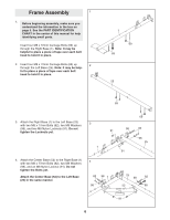
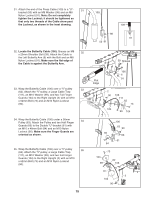
12. Attach the Left Top Frame (36) to the Right Top Frame (5) with four M8 x 77mm Bolts (82), two M8 Washers (98), a Support Plate (31), and four M8 Nylon Locknuts (91). Do not tighten the Locknuts yet. 12 91 31 36 91 82 98 82 98 5 13. Attach the Left Top Frame (36) to the Left Upright (26) with two M8 x 77mm Bolts (82), a Support 13 Plate (31), and two M8 Nylon Locknuts (91). Do not tighten the Locknuts yet. 91 82 36 31 91 91 26 14. Orient the Butterfly Frame (14) as shown. Attach the Butterfly Frame to the Right Upright (2) with two M8 x 70mm Bolts (85), two M8 Washers (98), and two M8 Nylon Locknuts (91). Do not tighten the Locknuts yet. Attach the Butterfly Frame (14) to the Right Top Frame (5) with two M8 x 77mm Bolts (82), two M8 Washers (98), and two M8 Nylon Locknuts (91). Tighten the M8 Nylon Locknuts (91) used in steps 3-14. 14 82 98 98 5 91 91 98 85 98 91 2 14 Arm Assembly 15. Wet the lower end of the Left Butterfly Arm (6) with soapy water. Slide a Large Foam Pad (15) onto the Left Butterfly Arm. Note: an entire grease packet should be used for this step. Grease an M10 x 85mm Bolt (74) and the indicated edges of two Arm Bushing (23) with a grease packet. Attach the Left Butterfly Arm (6) to the Butterfly Frame (14) with the Bolt (74), an M10 Large Washer (100), the two Arm Bushings, and an M10 Nylon Locknut (90). Make sure the bolt head fits inside of the hole in the Butterfly Frame. 15 7 74-Grease Grease 23 14 100 90 23 Grease 6 15 Repeat this step with the Right Butterfly Arm (7). 10
-
 1
1 -
2
-
3
-
4
-
 5
5 -
 6
6 -
 7
7 -
 8
8 -
 9
9 -
 10
10 -
 11
11 -
 12
12 -
 13
13 -
 14
14 -
 15
15 -
16
-
17
-
18
-
19
-
20
-
21
-
22
-
23
-
24
-
25
-
26
-
27
-
28
-
29
-
30
-
31
-
32
-
33
-
34
-
35
-
36
-
37
 |
 |
