Weider Pro 4250 English Manual - Page 8
Attach the Left Seat Frame 27 to the Left Base - weight system
 |
View all Weider Pro 4250 manuals
Add to My Manuals
Save this manual to your list of manuals |
Page 8 highlights
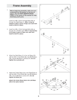
7. Attach the Left Seat Frame (27) to the Left Base (25) with the two indicated M8 x 72mm Carriage Bolts (69) and two M8 Nylon Locknuts (91). Do not tighten the Locknuts yet. 7 98 91 26 82 Attach the Left Seat Frame (27) to the Left Upright (26) with two M8 x 77mm Bolts (82), two M8 Washers (98), and two M8 Nylon Locknuts 98 82 27 (91). Do not tighten the Locknuts yet. 25 91 91 8. Orient the Weight Guides (44) with the indicated 8 holes closer to the bottom. Attach the Weight Guides inside of the Center Base (52) with two M8 x 77mm Bolts (82), four M8 Washers (98), and two M8 Nylon Locknuts (91). 69 44 44 Hole Hole 82 82 98 98 52 98 91 98 91 8
-
 1
1 -
2
-
 3
3 -
 4
4 -
 5
5 -
 6
6 -
 7
7 -
 8
8 -
 9
9 -
 10
10 -
 11
11 -
 12
12 -
 13
13 -
14
-
15
-
16
-
17
-
18
-
19
-
20
-
21
-
22
-
23
-
24
-
25
-
26
-
27
-
28
-
29
-
30
-
31
-
32
-
33
-
34
-
35
-
36
-
37
 |
 |

8
7.
Attach the Left Seat Frame (27) to the Left Base
(25) with the two indicated M8 x 72mm Carriage
Bolts (69) and two M8 Nylon Locknuts (91).
Do
not tighten the Locknuts yet.
Attach the Left Seat Frame (27) to the Left
Upright (26) with two M8 x 77mm Bolts (82), two
M8 Washers (98), and two M8 Nylon Locknuts
(91).
Do not tighten the Locknuts yet.
8.
Orient the Weight Guides (44) with the indicated
holes closer to the bottom. Attach the Weight
Guides inside of the Center Base (52) with two
M8 x 77mm Bolts (82), four M8 Washers (98),
and two M8 Nylon Locknuts (91).
7
8
27
82
82
25
26
91
69
91
98
98
91
44
44
Hole
Hole
82
82
98
98
98
98
52
91
91