Weider Pro 4250 English Manual - Page 20
Seat Assembly
 |
View all Weider Pro 4250 manuals
Add to My Manuals
Save this manual to your list of manuals |
Page 20 highlights
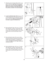
55. Wrap the Ab Cable (107) over a 90mm Pulley 55 (63). Attach the Pulley and the two Quarter Finger Guards (105) to the Right Upright (2) with an M10 x 106mm Bolt (72), an M10 Washer (99), and an M10 Nylon Locknut (90). Make sure that the rod is inserted through both Finger Guards and is over the Cable. 56. Tighten the Weight Cable (110) into the Weight Tube (not shown) until all the slack is taken out of 56 the cables. Tighten the M12 Nut (49) on the Weight Cable against the M12 Washer (33). 90 99 107 2 Rod 105 63 105 72 110 33 49 Seat Assembly 57 26 88 53 113 57. Attach the Press Backrest (113) to the Backrest Frame (53) with two M6 x 16mm Screws (88), an M6 x 35mm Screw (78), and an M6 Washer (97). 43 Slide the Backrest Frame (53) into the Left Upright (26). Engage the Knob (43) into the Upright and Backrest Frame, and turn it clockwise until it is tight. 78 97 58. Attach a Seat (8) to the Left Seat Frame (27) with 58 four M6 x 16mm Screws (88). 8 Repeat this step with the other Seat (8) and the Right Seat Frame (not shown). 27 88 88 20
-
 1
1 -
2
-
3
-
4
-
5
-
6
-
7
-
8
-
9
-
10
-
11
-
12
-
13
-
14
-
 15
15 -
 16
16 -
 17
17 -
 18
18 -
 19
19 -
 20
20 -
 21
21 -
 22
22 -
 23
23 -
 24
24 -
 25
25 -
26
-
27
-
28
-
29
-
30
-
31
-
32
-
33
-
34
-
35
-
36
-
37
 |
 |
