Weider Pro 4250 English Manual - Page 6
Frame Assembly - manual
 |
View all Weider Pro 4250 manuals
Add to My Manuals
Save this manual to your list of manuals |
Page 6 highlights
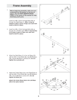
Frame Assembly 1 1. Before beginning assembly, make sure you understand the information in the box on page 5. See the PART IDENTIFICATION CHART in the center of this manual for help identifying small parts. Insert four M8 x 72mm Carriage Bolts (69) up through the Right Base (1). Note: It may be helpful to place a piece of tape over each bolt head to hold it in place. 2. Insert four M8 x 72mm Carriage Bolts (69) up 2 through the Left Base (25). Note: It may be help- ful to place a piece of tape over each bolt head to hold it in place. 1 69 69 25 69 3. Attach the Right Base (1) to the Left Base (25) 3 with two M8 x 77mm Bolts (82), two M8 Washers (98), and two M8 Nylon Locknuts (91). Do not tighten the Locknuts yet. 91 1 4. Attach the Center Base (52) to the Right Base (1) with two M8 x 77mm Bolts (82), two M8 Washers (98), and an M8 Nylon Locknut (91). Do not tighten the Bolts yet. Attach the Center Base (52) to the Left Base (25) in the same manner. 4 82 98 1 98 69 98 91 82 98 25 25 98 82 52 98 91 6
-
 1
1 -
 2
2 -
 3
3 -
 4
4 -
 5
5 -
 6
6 -
 7
7 -
 8
8 -
 9
9 -
 10
10 -
 11
11 -
 12
12 -
13
-
14
-
15
-
16
-
17
-
18
-
19
-
20
-
21
-
22
-
23
-
24
-
25
-
26
-
27
-
28
-
29
-
30
-
31
-
32
-
33
-
34
-
35
-
36
-
37
 |
 |
