Weider Pro 4250 English Manual - Page 11
Attach a Press Arm Cap 34 to the Press Arm - system
 |
View all Weider Pro 4250 manuals
Add to My Manuals
Save this manual to your list of manuals |
Page 11 highlights
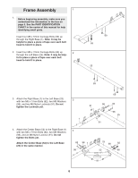
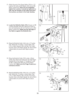
16. Attach the Leg Bumper (59) to the Right Seat Frame (3) with an M4 x 16mm Self-tapping Screw (89) and an M4 Washer (96). Grease an M10 x 72mm Bolt (60). Attach the Leg Lever (4) to the Right Seat Frame (3) with the Bolt and an M10 Nylon Locknut (90). Make sure the "U"-rod is on the indicated side of the Leg Lever. Do not overtighten the Locknut; the Leg Lever must be able to pivot easily. 16 4 "U"-rod 90 89 96 59 3 Grease 60 17. Grease an M10 x 106mm Bolt (72). Orient the Press Frame (29) so that the welded tube is on the side toward the Left Upright (26). Attach the Press Frame to the Left Base (25) with the Bolt and an M10 Nylon Locknut (90). Do not overtighten the Locknut; the Press Frame must be able to pivot easily. 17 Tube 26 90 29 Grease 72 25 18. Attach a Press Handle (32) to a Press Arm (30) 18 with an M10 x 65mm Bolt (77), two M10 Washers (99), two M10 x 12mm Spacers (101), and an M10 Nylon Locknut (90). Attach a Press Arm Cap (34) to the Press Arm (30) with an M10 x 45mm Button Bolt (81) and an M10 Large Washer (100). 81 100 Repeat this step with the other Press Arm (30). 34 32 30 90 99 101 101 99 30 77 11
-
 1
1 -
2
-
3
-
4
-
5
-
 6
6 -
 7
7 -
 8
8 -
 9
9 -
 10
10 -
 11
11 -
 12
12 -
 13
13 -
 14
14 -
 15
15 -
 16
16 -
17
-
18
-
19
-
20
-
21
-
22
-
23
-
24
-
25
-
26
-
27
-
28
-
29
-
30
-
31
-
32
-
33
-
34
-
35
-
36
-
37
 |
 |
