Weider Pro 435 Instruction Manual - Page 8
Caution, Warning
 |
View all Weider Pro 435 manuals
Add to My Manuals
Save this manual to your list of manuals |
Page 8 highlights
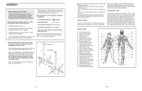
6. Lubricate an M10 x 70mm Bolt (18). Attach the 6 Leg Lever (4) to the Front Leg (8) with the Bolt and an M10 Nylon Locknut (19). Do not over- tighten the Nylon Locknut; the Leg Lever must be able to pivot easily. 19 4 18 Lubricate 8 7. Identify the Right and Left Backrest Frames (5, 42) by the position of the adjustment tubes, and orient them as shown. Tap two 25.4mm Square Inner Caps (12) into the ends of each Backrest Frame. Tap a 25mm x 50mm Inner Cap (36) into the bottom of each adjustment tube. Orient the Backrest (6) with the wide end on the side shown. Attach the Backrest to the Right and Left Backrest Frames (5, 42) with four M6 x 38mm Bolts (16) and four M6 Washers (25). Do not tighten the Bolts yet. 8. Lubricate the M10 x 175mm Bolt (17). Attach the Backrest Frames (5, 42) to the Bench Frame (2) with the Bolt, two M10 Washers (24), and an M10 Nylon Locknut (19). Do not overtighten the Nylon Locknut; the Backrest (6) must be able to pivot easily. Secure the Backrest (6) to the Bench Frame (2) by inserting the Adjustment Pin (32) through the tube in the Bench Frame and a set of holes in the adjustment tubes. Make sure that the Adjustment Pin is completely inserted through both adjustment tubes. Tighten the four M6 x 38mm Bolts (16) used in step 7. 7 6 Wide End 12 5 12 25 16 36 8 42 25 25 16 Adjustment Tubes 25 16 6 5 32 42 Adjustment Tubes 17 24 Tube 24 2 19 8 ATTACHING THE LAT BAR Some exercises require the use of the Lat Bar (60). Attach the Lat Bar to the Cable (58) with a Cable Clip (57). WARNING: Always remove the Lat Bar (60) when performing an exercise that does not require it. 58 57 60 ATTACHING WEIGHTS TO THE WEIGHT CARRIAGE OR THE LEG LEVER Weights 47 If you will be using 28mm weights (not included), first slide the Weight Tube Adaptors (69) onto the weight 53 48 tubes of the Weight Carriage (48) or the Leg Lever (4). 69 To use the Lat Tower (47) or the Leg Lever (4), slide the desired amount of weight (not included) onto the weight tubes of the Weight Carriage (48) or the Leg Lever. Secure the weights with the Weight Clips (53). WARNING: Do not place more than 59 kg (130 lbs.) on the Lat Tower (47) or the Leg Lever (4). 4 69 53 STORING THE WEIGHT BENCH To store your weight bench, remove the M10 x 57mm Adjustment Knob (33) and the Ring Pin (43) from the Crossbar (3). Lift the Front Leg (8) as far as it will go. Reinsert the Ring Pin into the bracket on the Crossbar; the Ring Pin will prevent the bench from unfolding. Note: The Backrest (6) must be adjusted to one of the incline positions (see ADJUSTING THE BACKREST, on page 11). CAUTION: To fold the weight bench, the holes in the Stabilisers (45, 46) must be at least 50 cm (20 in.) from the wall, and the Lat Bar (60) must be removed. 8 6 Hole 45 43 33 3 46 Hole 13
-
 1
1 -
2
-
 3
3 -
 4
4 -
 5
5 -
 6
6 -
 7
7 -
 8
8 -
 9
9 -
 10
10
 |
 |
