Weider Pro 435 Instruction Manual - Page 9
Warning
 |
View all Weider Pro 435 manuals
Add to My Manuals
Save this manual to your list of manuals |
Page 9 highlights
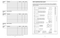
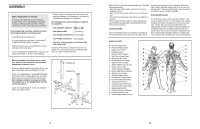
STORING THE CURL PAD AND LAT TOWER When the Curl Pad (27) or the Lat Tower (not shown) is not in use, it can be stored in the storage tube on the Left Stabiliser (46). However, for some exercises, you should store these parts away from the weight bench so they do not interfere with your exercise. ADJUSTING THE UPRIGHTS To adjust the Uprights (1), unscrew the M10 x 62mm Adjustment Knobs (30) and slide the Uprights to the desired position. Re-tighten the Adjustment Knobs into the Upright Bases (7) and the Uprights. WARNING: Always set both Uprights (1) at the same height. Make sure the M10 x 62mm Adjustment Knobs (30) are fully tightened into the Upright Bases (7) and Uprights. USING THE BARBELL HOOKS To change weights while your barbell (not included) is on the Uprights (1), secure the barbell with the Barbell Hooks (56, 61 [not shown]). To do this, rotate the Barbell Hooks over the barbell. This will reduce the possibility of the barbell tipping while you are changing weights. 27 Storage Tube 46 1 30 7 1 56 12 9. Orient the Seat (11) with the wide end on the side shown. Attach the Seat to the Bench Frame (2) with four M6 x 16mm Bolts (15). 9 11 Wide End 10. Insert 19mm Round Inner Caps (9) into both ends of the three Pad Tubes (10). Slide the Pad Tubes 10 22 into the holes in the Leg Lever (4) and the Front Leg (8). Slide two Foam Pads (22) onto each Pad 4 Tube. 22 2 15 15 8 9 10 9 11. Slide a Bushing (28) onto the bottom of each Upright (1). Be sure the tab is on the indicated side of the Bushing. Press a 60mm x 50mm Bushing (31) into the bottom of each Upright and secure it with two M4 x 8mm Screws (34). Attach the Right Barbell Hook (56) to an Upright (1) with a Bright M8 Washer (63) and a Bright M8 Nylon Locknut (62). Attach the Left Barbell Hook (61) to the other side of the other Upright in the same manner. Orient the two Uprights as shown. 12. Press the tabs on the Bushing (28) into the slots in the left Upright (1). Slide the Upright and the Bushing into the left Upright Base (7), so that the tabs snap into the slots in the Upright Base. Note: Be careful not to pinch your fingers Align one of the adjustment holes in the Upright (1) with the hole in the Upright Base (7). Tighten an M10 x 62mm Adjustment Knob (30) into the holes. Attach the right Upright (1) to the right Upright Base (7) in the same manner. Note: Always set both Uprights at the same height. WARNING: Do not insert the M10 x 62mm Adjustment Knob (30) through the slot in the Upright (1). 11 62 63 1 28 34 31 12 1 28 7 9 22 10 9 56 61 1 Tab 34 Adjustment Hole 1 28 Tab Slot 7 30 9
-
 1
1 -
2
-
3
-
 4
4 -
 5
5 -
 6
6 -
 7
7 -
 8
8 -
 9
9 -
 10
10
 |
 |
