Weider Pro 4900 English Manual
Weider Pro 4900 Manual
 |
View all Weider Pro 4900 manuals
Add to My Manuals
Save this manual to your list of manuals |
Weider Pro 4900 manual content summary:
- Weider Pro 4900 | English Manual - Page 1
. Write the serial number in the space above for reference. WEIGHT SYSTEM EXERCISER User's Manual Serial Number Decal (under seat) • Assembly • Adjustments • Troubleshooting • Part List and Drawing CAUTION Read all precautions and instructions in this manual before using this equipment. Save this - Weider Pro 4900 | English Manual - Page 2
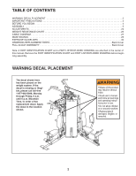
PRECAUTIONS 3 BEFORE YOU BEGIN 4 ASSEMBLY 5 ADJUSTMENTS 24 WEIGHT RESISTANCE CHART 26 CABLE DIAGRAM 27 MAINTENANCE 29 EXERCISE GUIDELINES 30 ORDERING REPLACEMENT PARTS Back Cover FULL 90-DAY WARRANTY Back Cover Note: A PART IDENTIFICATION CHART and a PART LIST/EXPLODED DRAWING are attached - Weider Pro 4900 | English Manual - Page 3
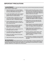
does not use the lat bar. 7. The weight system is designed to support a maximum user weight of 300 pounds. 8. Always wear athletic shoes for foot protection while exercising. 9. Keep hands and feet away from moving parts. 15. Keep the resistance system indoors, away from moisture and dust. Do not - Weider Pro 4900 | English Manual - Page 4
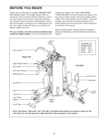
BEFORE YOU BEGIN Thank you for selecting the versatile WEIDER® PRO 4900 weight system. The weight system offers an impressive array of weight stations designed to develop every major muscle group of the body. Whether your goal is to tone your body, build dramatic muscle size and strength, - Weider Pro 4900 | English Manual - Page 5
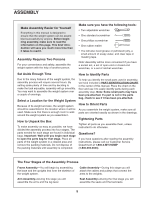
reading the assembly instructions, please call our Customer Service Department at 1-800-4-MY-HOME® (1-800-469-4663). The Four Stages of the Assembly Process Frame Assembly-You will begin by assembling the base and the uprights that form the skeleton of the weight system. Cable Assembly-During - Weider Pro 4900 | English Manual - Page 6
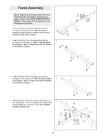
Frame Assembly 1 1. Before beginning assembly, make sure you understand the information in the box on page 5. Refer to the PART IDENTIFICATION CHART in the center of this manual for help identifying small parts. Insert four M8 x 75mm Carriage Bolts (84) up through the Right Base (1). Note: It may - Weider Pro 4900 | English Manual - Page 7
5. Attach the Rear Upright (6) to the Rear Base (3) 5 with the two indicated M8 x 75mm Carriage Bolts (84) and two M8 Nylon Locknuts (115). Do not tighten the Locknuts yet. 6 6. Attach the Right Upright (4) to the Right Base (1) 6 with the two indicated M8 x 75mm Carriage Bolts (84) and two - Weider Pro 4900 | English Manual - Page 8
7. Attach the Left Upright (5) to the Left Base (2) 7 with the two indicated M8 x 75mm Carriage Bolts (84) and two M8 Nylon Locknuts (115). Do not tighten the Locknuts yet. 5 115 8. Hold the Left Top Frame (8) between the Left Upright (5) and the Rear Upright (6). Attach the Pull-up Arm (19) - Weider Pro 4900 | English Manual - Page 9
(136), which have the lock holes closer to the center than the Rear Weight Guides (24). Orient the Weight Guides with the holes closer to the bottom. 10 136 Attach the Front Weight Guides (136) to the Right 24 Base (1) with an M10 x 155mm Bolt (130), two M10 Washers (116), and an M10 Nylon - Weider Pro 4900 | English Manual - Page 10
) to the Right Top Frame (7) with two M10 x 38mm Screws (82) and two M10 Washers (116). Repeat this step with the Rear Weight Guides (24). 12 24 82 116 7 82 116 136 13. Orient the Butterfly Frame (22) as shown. Attach the Butterfly Frame to the Right Upright (4) with - Weider Pro 4900 | English Manual - Page 11
Arm Assembly 16 16. Grease an M10 x 108mm Bolt (99). Orient the Press Frame (13) as shown. Attach the Press Frame to the Left Base (2) with the - Weider Pro 4900 | English Manual - Page 12
19. Attach the Leg Bumper (76) to the Right Seat 19 Frame (9) with an M4 x 16mm Self-tapping Screw (113) and an M4 Washer (131). 114 Grease an M10 x 75mm Bolt (104). Attach the Leg Lever (11) to the Right Seat Frame (9) with the Bolt and an M10 Nylon Locknut (114). Make sure the "U"-rod is on - Weider Pro 4900 | English Manual - Page 13
22. Refer to the CABLE DIAGRAMS on pages 27 and 28 as you assemble the cables and to identify the cables. Locate the Lat Cable (71). Route the Cable up through the Right Top Frame (7) and over a 90mm Pulley (39). Make sure the Cable is between the Pulley and the rod in the Top Frame. Attach the - Weider Pro 4900 | English Manual - Page 14
Washer (116), and an M10 Nylon Locknut (114). Make sure that the rod is inserted through both Quarter Guards and is over the Cable. 31. Wrap the Ab Cable (72) under a 90mm Pulley 31 (39). Attach the Pulley and two Half Finger Guards (42) to the Double "U"-bracket (52) with an M10 - Weider Pro 4900 | English Manual - Page 15
(90) and an M10 Nylon Locknut (114). Make sure the Cable Trap is oriented to hold the Cable in the groove of the Pulley. 4 43 49 40 116 43 72 Bolt (90) and an M10 Nylon Locknut (114). Make sure the Cable Trap is oriented to hold the Cable in the groove of the Pulley. 90 43 116 72 40 49 - Weider Pro 4900 | English Manual - Page 16
an M10 x 48mm Bolt (101) and an M10 Nylon Locknut (114). Make sure the Finger Guards are oriented as shown. 40. Wrap the Leg Lever Cable (70) over a 90mm 40 Pulley (39). Attach the Pulley and two Half Finger Guards (42) to the Double "U"-bracket (52) with an M10 x 48mm Bolt - Weider Pro 4900 | English Manual - Page 17
x 52mm Bolt (102) and an M10 Nylon Locknut (114). Make sure the Cable Trap and Finger Guards are oriented as shown and that the bracket is between the and the Finger Guard next to the Locknut. 45. Route the Leg Lever Cable (70) up through the 45 Right Top Frame (7), over a115mm Pulley (41 - Weider Pro 4900 | English Manual - Page 18
. Set an M12 Washer (129) on top of the Short 46 Weight Tube (123). Thread an M12 Nut (128) all the way onto the Leg Lever Cable (70). Thread the Leg Lever Cable (70) into the Short Weight Tube (123). Tighten the M12 Nut (128) against the M12 Washer (129). 47. Locate the Right Stack Cable - Weider Pro 4900 | English Manual - Page 19
Spacer (124), and an M10 Nylon Locknut (114). Make sure the 16mm Spacer and the Small Cable Trap are on the same side of the Pulley. 52. Set an M12 Washer (129) on top of the Long 52 Weight Tube (36). Thread an M12 Nut (128) all the way onto the Right Stack - Weider Pro 4900 | English Manual - Page 20
Washer (116) to the Left Upright (5) with an M10 x 108mm Bolt (99), an M10 Washer (116), and an M10 Nylon Locknut (114). Make sure the Cable Trap and Finger Guards are oriented as shown. 56 42 48 5 114 116 39 69 42 99 116 57. Wrap the Press - Weider Pro 4900 | English Manual - Page 21
complete- ly tighten the Locknut; it should be tightened so that only two threads of the Cable show 115 past the Locknut, as shown in the inset draw- ing. 117 50 50 69 115 Seat Assembly 62 62. Attach the Seat (29) with the serial number decal on the bottom to the - Weider Pro 4900 | English Manual - Page 22
65. Attach the Lock Plate (80) to the Right Seat 65 Frame (9) with an M8 x 69mm Shoulder Bolt (87), an M8 Washer (117), and an M8 Nylon Locknut (115). Do not overtighten the Locknut; the Lock Plate must be able to pivot easily. Attach the Leg Pin (83) to the Right Seat Frame (9) with an M4 x - Weider Pro 4900 | English Manual - Page 23
over the pulleys. If one of the cables does not move smoothly, find and correct the problem. IMPORTANT: If the cables are not properly installed, they may be damaged when heavy weight is used. See the CABLE DIAGRAMS on pages 26 and 27 of this manual for proper cable routing. If there is any slack in - Weider Pro 4900 | English Manual - Page 24
get the most benefit from your exercise program. Also, refer to the accompanying exercise guide to see the correct form for each exercise. Make sure all parts are properly tightened each time the weight system is used. Replace any worn parts immediately. The weight system can be cleaned with a damp - Weider Pro 4900 | English Manual - Page 25
by inserting a Lock Pin (44) through a Weight Guide (24 or 136) and securing the Lock (45) onto the Lock Pin. 24 or 136 45 44 LOCKING THE DIP ASSIST Make sure the Dip Assist (21) is locked when performing an exercise that does not require it. To lock the Dip Assist, engage the - Weider Pro 4900 | English Manual - Page 26
WEIGHT RESISTANCE CHART The chart below shows the approximate weight resistance at each exercise station. "Top" refers to the 6 lb. top weight. The other numbers refer to the 12.5 lb. weight plates. Weight resistance shown for the butterfly arm station is for each arm. Note: The actual resistance - Weider Pro 4900 | English Manual - Page 27
of the Right Stack Cable (68), the Press Cable (69), the Leg Lever Cable (70), the Lat Cable (71), and the Ab Cable (72). Use the diagram to make sure that the cables and the cable traps have been assembled correctly. If the cables have not been correctly routed, the weight bench will not function - Weider Pro 4900 | English Manual - Page 28
7 6 5 4 Lat Cable (71) 6 Length: 16 feet 5 2 4 1 3 8 7 3 9 1 Ab Cable (72) Length: 10 feet 3 inches 2 10 6 8 Leg Lever Cable (70) 2 Length: 21 feet 11 inches 1 4 3 7 5 28 - Weider Pro 4900 | English Manual - Page 29
parts immediately. The weight system can be cleaned with a damp cloth and a mild, non-abrasive detergent. Do not use solvents. TIGHTENING THE CABLES Woven cable, the type of cable used on the weight system, can stretch slightly when it is first used. If there is slack in the cables before resistance - Weider Pro 4900 | English Manual - Page 30
without discomfort. Rest for 1 minute after each set. Work your muscles by completing more sets rather than by using high amounts of resistance. Weight Loss To lose weight, use a low amount of resistance and increase the number of repetitions in each set. Exercise for 20 to 30 minutes, resting for - Weider Pro 4900 | English Manual - Page 31
at the end of each workout is an effective way to increase flexibility. STAYING MOTIVATED For motivation, keep a record of each workout. List the date, the exercises performed, the resistance used, and the numbers of sets and repetitions completed. Record your weight and key body measurements at - Weider Pro 4900 | English Manual - Page 32
in assembly. The number in parentheses by each drawing is the key number of the part, from the PART LIST in the center of this manual. Note: Some small parts may have been pre-attached. If a part is not in the parts bag, check to see if it has been pre-attached. If a part is missing, call toll-free - Weider Pro 4900 | English Manual - Page 33
M6 Locknut (135) M8 Nylon Locknut (115) M10 Nylon Locknut (114) M12 Nut (128) M8 Washer (117) M10 Washer (116) M12 Washer (129) M10 Large Washer (134) M10 x 77mm Bolt (133) M10 x 75mm Bolt (104) M8 x 72mm Bolt (91) M8 x 70mm Bolt (97) M8 x 69mm Shoulder Bolt (87) M10 x 68mm Bolt (93) M10 x 65mm - Weider Pro 4900 | English Manual - Page 34
PART LIST-Model No. 831.154031 Key No Assist 22 1 Butterfly Frame 23 1 Foot Plate 24 2 Rear Weight Guide 25 1 Rear Shroud 26 4 Shroud Cover 27 1 Backrest Frame Weight Bumper Weight Tube Bumper Dip Assist Latch Right Stack Cable Press Cable Leg Lever Cable Lat Cable Ab Cable - Weider Pro 4900 | English Manual - Page 35
Inner Cap User's Manual Exercise Guide Allen Wrench Grease Packet Note: "#" indicates a non-illustrated part. Specifications are subject to change without notice. See the back cover of the user's manual for information about ordering replacement parts. If a part is missing, call toll-free 1-877-992 - Weider Pro 4900 | English Manual - Page 36
EXPLODED DRAWING-Model No. 831.154031 R0804A 43 116 40 49 59 17 59 90 43 43 40 59 43 92 115 90 115 92 22 88 116 134 114 72 49 57 114 134 115 114 79 55 59 114 55 115 18 43 49 40 43 91 117 90 114 43 95 115 99 114 116 116 39 40 95 49 72 43 116 114 85 58 93 32 79 - Weider Pro 4900 | English Manual - Page 37
54 42 105 134 39 89 48 37 114 115 105 117 42 134 102 5 69 50 56 56 114 116 16 16 75 75 116 96 85 140 121 27 120 117 94 117 115 139 132 93 99 140 116 42 39116 115 49 40 116 48 42 42 114 42 42 39 114 116 42 116 115 102 114 116 14 97 75 75 33 116 96 97 42 39 - Weider Pro 4900 | English Manual - Page 38
EXPLODED DRAWING-Model No. 831.154031 R0804A 30 55 67 116 61 53 75 43 74 43 74 114 39 48 116 114 85 116 116 114 53 61 85 89 117 19 107 108 116 116 61 54 108 116 21 114 61 126 62 42 114 48 64 55 39 108 51 42 126 62 89 117 6 42 51 48 102 39 42 20 71 88 63 112 - Weider Pro 4900 | English Manual - Page 39
26 109 132 109 132 25 26 109 132 109 132 111 116 77 94 41 77 94 135 114 116 115 117 117 111 116 135 127 54 7 116 111 77 39 77 39 71 116 114 77 77 77 116 82 39 77 114 116 77 73 125 73 48 39 115 39 115 117 114 111 94 94 117 115 68 115 135 114 77 116 77 115 114 116 - Weider Pro 4900 | English Manual - Page 40
the nearest Sears Service Center throughout the United States and Sears will repair or replace the WEIGHT SYSTEM EXERCISER, free of charge. This warranty does not apply when the WEIGHT SYSTEM EXERCISER is used commercially or for rental purposes. This warranty gives you specific legal rights, and
-
 1
1 -
 2
2 -
 3
3 -
 4
4 -
 5
5 -
 6
6 -
 7
7 -
8
-
9
-
10
-
11
-
12
-
13
-
14
-
15
-
16
-
17
-
18
-
19
-
20
-
21
-
22
-
23
-
24
-
25
-
26
-
27
-
28
-
29
-
30
-
31
-
32
-
33
-
34
-
35
-
36
-
37
-
38
-
39
-
40
 |
 |

CAUTION
Read all precautions and instruc-
tions in this manual before using
this equipment. Save this manu-
al for future reference.
WEIGHT SYSTEM EXERCISER
User’s Manual
Model No. 831.154031
Serial No.
Write the serial number in the
space above for reference.
Serial Number Decal (under seat)
Sears, Roebuck and Co., Hoffman Estates, IL 60179
• Assembly
• Adjustments
• Troubleshooting
• Part List and Drawing