Weider Pro 525 English Manual - Page 7
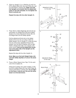
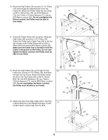
Note: Make sure that both Weight Rests 30
 |
View all Weider Pro 525 manuals
Add to My Manuals
Save this manual to your list of manuals |
Page 7 highlights
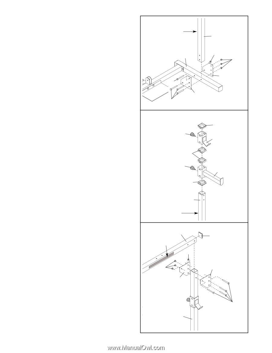
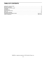
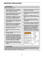
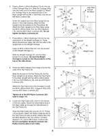
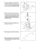
3. Attach an Upright (1) to a Stabilizer (5) with four M10 x 80mm Bolts (22), two Joint Plates (9), and four M10 Nylon Locknuts (20). Make sure that the Uprights are oriented with the adjustment holes on the side indicated. Do not tighten the Nylon Locknuts yet. Repeat this step with the other Upright (1). 3 Adjustment Holes on this side 5 1 20 20 4. Press 75mm x 65mm Bushings (32) into the top and bottom of a Weight Rest (30) and a Safety Spotter (31). Screw Adjustment Knobs (33) into the Weight Rest and the Safety Spotter. Pull the Adjustment Knob (33) on the Safety Spotter (31) out as far as it will go. Slide the Safety Spotter over an Upright (1). Snap the Knob into one of the lower adjustment holes in the Upright. Turn the Knob clockwise until it is tight. Attach a Weight Rest (30) to the Upright in the same manner. Be sure the Adjustment Knobs are on the same side of the Uprights as the adjustment holes. Repeat this step with the other Upright (1). Note: Make sure that both Weight Rests (30) and both Safety Spotters (31) are at the same height. 5. Press a 60mm Square Inner Cap (11) into each end of the Crossbar (4). Attach the Crossbar (4) to each Upright (1) with four M10 x 80mm Bolts (22), two Joint Plates (9), and four M10 Nylon Locknuts (20). Do not tighten the Nylon Locknuts yet. Be sure the name decal is on the side shown. 22 9 22 4 33 32 33 32 1 Adjustment Holes on this side 5 4 Name Decal 20 20 9 9 32 30 31 11 9 22 1 7
-
 1
1 -
 2
2 -
 3
3 -
 4
4 -
 5
5 -
 6
6 -
 7
7 -
 8
8 -
 9
9 -
 10
10 -
 11
11 -
 12
12 -
13
-
14
-
15
-
16
-
17
-
18
-
19
-
20
 |
 |