Weider Pro 525 English Manual - Page 8
Tighten all of the M10 Nylon Locknuts 20
 |
View all Weider Pro 525 manuals
Add to My Manuals
Save this manual to your list of manuals |
Page 8 highlights
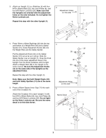
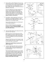
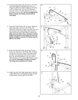
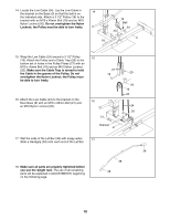
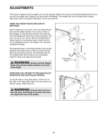
6. Press a 60mm x 50mm Bushing (13) into the top of the Carriage Stop (14). Slide the Carriage Stop onto the lower end of the Rear Upright (2). Attach the Carriage Stop to the indicated hole in the Rear Upright with an M8 x 70mm Bolt (25) and an M8 Nylon Locknut (28). Orient the angled top of the Rear Upright (2) as shown in the inset drawing. Slide the Rear Upright onto the bracket on the Rear Base (8). Attach the Rear Upright to the Rear Base using two M10 x 65mm Bolts (19), four M10 Washers (15), and two M10 Nylon Locknuts (20). Do not tighten the Nylon Locknuts yet. 7. Press 60mm x 50mm Bushings (13) into the top and bottom of the Weight Carriage (7). Press 25mm Round Inner Caps (40) into the ends of the weight tube on the Weight Carriage. Insert an M10 x 20mm Bolt (21) into the bracket on the Weight Carriage (7). Slide the Weight Carriage (7) onto the Rear Upright (2) as shown. Be sure the Weight Carriage is turned so that the bracket is at the top on the side shown. 8. Press two 50mm Square Inner Caps (12) into the ends of the Top Frame (6). Slide the bracket on the Top Frame (6) into the Rear Upright (2) as shown. Attach the Top Frame to the Rear Upright with two M10 x 65mm Bolts (19), four M10 Washers (15), and two M10 Nylon Locknuts (20). Attach the Top Frame (6) to the Crossbar (4) with two M10 x 80mm Bolts (22), a Support Plate (29), and two M10 Nylon Locknuts (20). Tighten all of the M10 Nylon Locknuts (20) used in steps 1-8. 9. Locate the High Cable (23), which is the shorter of the two cables. Route the metal-sleeve end of the High Cable up through the indicated slot in the Top Frame (6). Wrap the High Cable (23) around a 3 1/2" Pulley (16) as shown. Attach the Pulley inside the slot in the Top Frame (6) with an M10 x 65mm Bolt (19), two M10 Washers (15), two 15mm x 10.5mm Spacers (17), and an M10 Nylon Locknut (20). Do not overtighten the Nylon Locknut; the Pulley must be able to turn freely. 6 Hole 15 19 13 25 20 15 2 28 14 Base High Side Toward the Base 2 8 7 13 Bracket 21 40 40 Weight Tube 7 13 2 8 12 6 20 12 20 15 15 19 2 29 4 22 9 16 17 17 6 19 15 20 15 23 8
-
 1
1 -
2
-
 3
3 -
 4
4 -
 5
5 -
 6
6 -
 7
7 -
 8
8 -
 9
9 -
 10
10 -
 11
11 -
 12
12 -
 13
13 -
14
-
15
-
16
-
17
-
18
-
19
-
20
 |
 |
