Weider Pro 9635 English Manual - Page 8
Screws 41 and the M10 Locknut 37. - weight amounts
 |
View all Weider Pro 9635 manuals
Add to My Manuals
Save this manual to your list of manuals |
Page 8 highlights
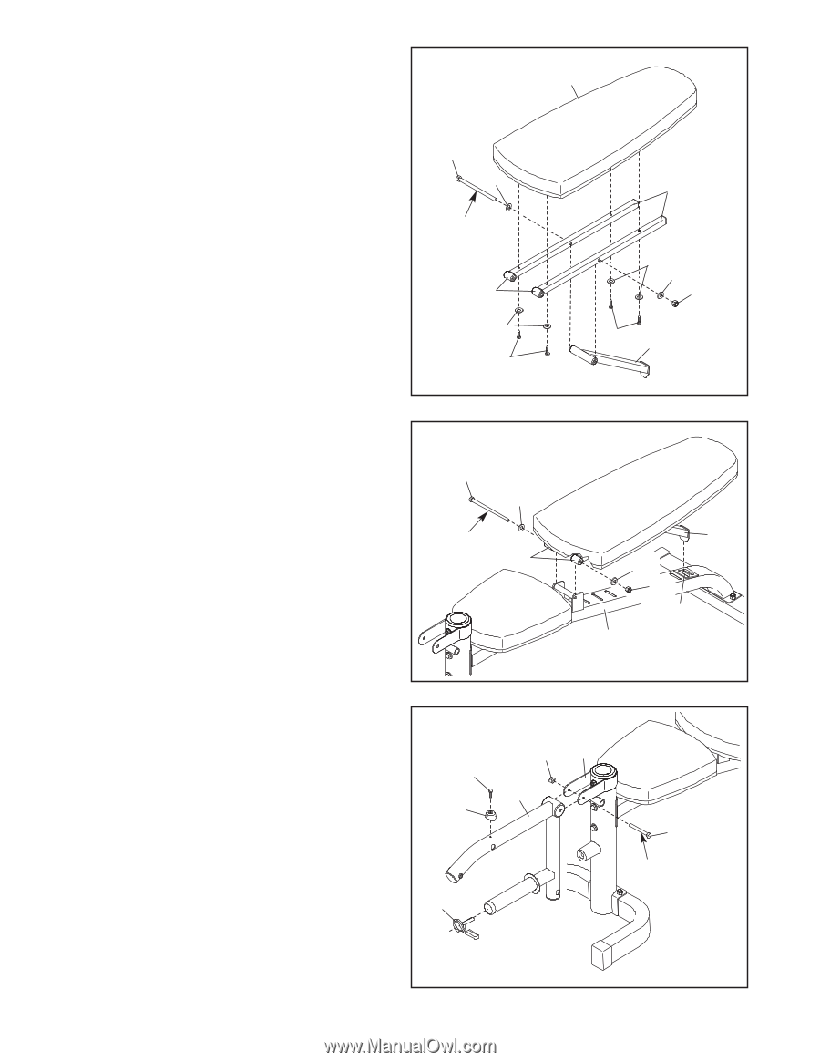
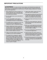
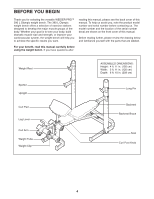
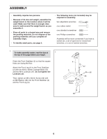
5. Orient the Backrest Frames (16) so that the welded tubes are in the positions shown. Apply a small amount of the included grease to an M10 x 180mm Bolt (54). Attach the Backrest Brace (15) to the Backrest Frames (16) with the Bolt, two M10 Washers (35), and an M10 Locknut (37). Do not tighten the Locknut yet. Orient the Backrest (19) as shown. Attach the Backrest (19) to the Backrest Frames (16) with four M6 x 48mm Screws (41) and four M6 Washers (42). Do not tighten the Screws yet. 5 54 35 Grease Welded Tubes 42 41 19 16 42 35 37 41 15 6. Apply a small amount of grease to an M10 x 192mm Bolt (43). Attach the Backrest Frames (16) to the Frame (1) with the Bolt, two M10 Washers (35), and an M10 Locknut (37). Do not overtighten the Locknut; the Backrest Frames should pivot easily. Insert the end of the Backrest Brace (15) into one of the slots in the Frame (1). See step 5. Tighten the four M6 x 48mm Screws (41) and the M10 Locknut (37). Do not overtighten the Locknut; the Backrest Brace (15) should pivot easily. 6 43 35 Grease 16 15 35 37 Slot 1 7. Apply a small amount of grease to an M10 x 85mm Bolt (45). Attach the Leg Lever (5) to the Front Leg (4) with the Bolt and an M10 Locknut (37). Do not overtighten the Locknut; the Leg Lever should pivot easily. Attach the Curl Arm Bumper (46) to the Leg Lever (5) with an ST4.2 x 20mm Screw (53). Then, attach the Weight Clip (8) to the weight tube on the Leg Lever (5). 7 53 46 8 37 4 5 45 Grease 8
-
 1
1 -
2
-
 3
3 -
 4
4 -
 5
5 -
 6
6 -
 7
7 -
 8
8 -
 9
9 -
 10
10 -
 11
11 -
 12
12 -
 13
13 -
14
-
15
-
16
-
17
-
18
-
19
-
20
 |
 |