Weslo Momentum 7.0 Ex Elliptical English Manual - Page 6
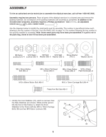
M10 x 70mm Carriage Bolts 34 and two M10 Nylon
 |
View all Weslo Momentum 7.0 Ex Elliptical manuals
Add to My Manuals
Save this manual to your list of manuals |
Page 6 highlights
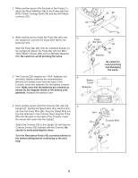
2. While another person lifts the back of the Frame (1), attach the Rear Stabilizer (28) to the Frame with two M10 x 70mm Carriage Bolts (34) and two M10 Nylon Locknuts (33). 3. While another person holds the Pulse Bar (65) near the Upright (2), connect the Pulse Wire (64) to the pulse bar wire. Slide the Pulse Bar (65) onto the indicated bracket on the Upright (2). Attach the Pulse Bar with two M8 x 16mm Button Screws (68) and two M8 Split Washers (69). Be careful to avoid pinching the wires. 4. The Console (23) requires two "AAA" batteries (not included); alkaline batteries are recommended. Remove the battery cover from the back of the Console. Insert two batteries into the battery compartment. Make sure that the batteries are oriented as shown by the diagram inside of the battery compartment. Reattach the battery cover. 2 33 28 33 1 3 2 34 Pulse Bar Wire 64 Bracket 65 69 68 Be careful to avoid pinching and damaging the wires. 4 Battery Cover Batteries 23 5. Have another person hold the Console (23) near the 5 Upright (2). Identify the Speed Wire (44), which is thin- ner than the Pulse Wire (64). Plug the Speed Wire into the wire attached to the Console. Next, plug the Pulse Wire into the jack on the back of the Console. Insert the excess wire down into the Upright. Attach the Console (23) to the Upright (2) with the two Console Screws (63) included with the Console. Be careful to avoid pinching the wires. Turn the Resistance Knob (45) counterclockwise to the lowest setting before continuing to the next step. 23 Jack 64 Console Wire 44 45 63 2 6
-
 1
1 -
 2
2 -
 3
3 -
 4
4 -
 5
5 -
 6
6 -
 7
7 -
 8
8 -
 9
9 -
 10
10 -
 11
11 -
 12
12 -
13
-
14
-
15
-
16
 |
 |
