Weslo Pursuit G 3.1 Bike English Manual - Page 5
Part Identification Chart
 |
View all Weslo Pursuit G 3.1 Bike manuals
Add to My Manuals
Save this manual to your list of manuals |
Page 5 highlights
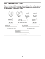
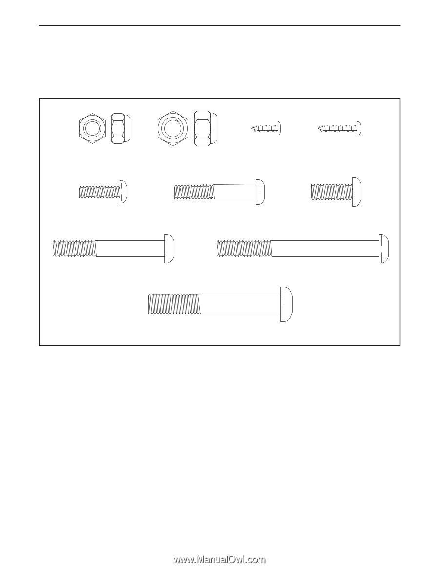
PART IDENTIFICATION CHART Use the drawings below to identify the small parts needed for assembly. The number in parentheses below each drawing is the key number of the part, from the PART LIST near the end of this manual. The number following the key number is the quantity needed for assembly. Note: If a part is not in the hardware kit, check to see if it has been preassembled. Extra parts may be included. M8 Locknut (35)–-2 M10 Locknut (45)–-2 M4 x 13mm Truss Screw (42)–-4 M4 x 19mm Screw (27)–-2 M6 x 20mm Screw (47)–-4 M6 x 40mm Screw (44)–-4 M8 x 20mm Screw (40)–-7 M8 x 55mm Screw (46)–-2 M8 x 80mm Bolt (39)–-2 M10 x 65mm Bolt (28)–-4 5
-
 1
1 -
 2
2 -
 3
3 -
 4
4 -
 5
5 -
 6
6 -
 7
7 -
 8
8 -
 9
9 -
 10
10 -
 11
11 -
12
-
13
-
14
-
15
-
16
-
17
-
18
-
19
-
20
 |
 |
5
M10 x 65mm Bolt (28)°4
M8 x 55mm Screw (46)°2
M8 x 80mm Bolt (39)°2
M8 x 20mm
Screw (40)°7
M6 x 20mm
Screw (47)°4
M6 x 40mm Screw (44)°4
M10 Locknut
(45)°2
M8 Locknut
(35)°2
M4 x 19mm
Screw (27)°2
M4 x 13mm
Truss Screw
(42)°4
PART IDENTIFICATION CHART
Use the drawings below to identify the small parts needed for assembly. The number in parentheses below each
drawing is the key number of the part, from the PART LIST near the end of this manual. The number following the
key number is the quantity needed for assembly.
Note: If a part is not in the hardware kit, check to see if it
has been preassembled. Extra parts may be included.