Yamaha AVC-50 AVC-50 OWNERS MANUAL
Yamaha AVC-50 Manual
 |
View all Yamaha AVC-50 manuals
Add to My Manuals
Save this manual to your list of manuals |
Yamaha AVC-50 manual content summary:
- Yamaha AVC-50 | AVC-50 OWNERS MANUAL - Page 1
the AVC-50 Stereo Amplifier. 50 Natural Sound Stereo Ainplifier 10 Audio Inputs. 4 Video Inputs Surround Sound Processor Sound Processor Rear Speaker Placement Remote Control Unit Battery Installation Controls Using the Remote Control Adding a Graphic Equalizer Specifications Troubleshooting - Yamaha AVC-50 | AVC-50 OWNERS MANUAL - Page 2
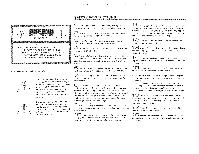
appliance has been dropped, or the cabinet damaged. .E 6 Servicing - The user should not attempt to service the appliance beyond those means described in the operating instructions. All other servicing should be referred to qualified service personnel. 1 7 Power Lines - An outdoor antenna should be - Yamaha AVC-50 | AVC-50 OWNERS MANUAL - Page 3
best possible sound reproduction, please read this manual carefully. 2. Choose the installation location of your amplifier carefully. Avoid the TROUBLESHOOTING section for advice on common operating errors before concluding that there is scmething wrong with your amplifier. 9. Keep this manual in - Yamaha AVC-50 | AVC-50 OWNERS MANUAL - Page 4
- Yamaha AVC-50 | AVC-50 OWNERS MANUAL - Page 5
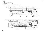
1 p iill4 Ni I Ir'' °_ iiVC ''''' 4. 0 Keep this page folded open for reference as you read this manual. Front Panel 9 0 oo e YAMAHA NATURAL SOUND STEREO ...LOW. AVC-50 Ilos 1 E•LECTOR D. E: t:Yi , CC /004. OW:A 10 yaw D,.014 . rwAra Lave. 0 n-vaiu Oa., 0.o..0 INPUT SELECTOR 0. vrAln - Yamaha AVC-50 | AVC-50 OWNERS MANUAL - Page 6
using the AVC-50 as a rear speaker amplifier, this SOUND Selectors These buttons are used to select the audio source to be sent to the audio REC OUT terminals, enabling audio recording of any source, even while monitoring another • BASS EXTENSION Switch This switch is used to activate a Yamaha - Yamaha AVC-50 | AVC-50 OWNERS MANUAL - Page 7
THEIR FUNCTiONS. jai 1,ic041W'0. AVC-50 ,4491*, (1) REMCTE CONTROL Cable Connectors Use these to connect compatible Yamaha components (with an H40 mark) to your amplifier for remote control of each component. The cables for each component are supplied with the AC-50. PHONO-Connect to a turntable - Yamaha AVC-50 | AVC-50 OWNERS MANUAL - Page 8
AVC3-5O 'SYSTEM POSSIMIT,IES _ There are three basic system configurations in which the AVC-50 may be used. (1) The AVC-50 as Integrated Amplifier in a 4-Speaker System In this configuration, the AVC-50 functions as a preamplifier, controlling all audio and video components in your system, and - Yamaha AVC-50 | AVC-50 OWNERS MANUAL - Page 9
.3pea,cer'S • 4-)1; r 4 +0 4 / r 4 40 1 40. Speaker terminals]. INPUT terminal Amplifier INPUT terminal .......-. .6---_rl riT31713 6o_:o03i Speaker terminals Amplifier 0 0 1'4 1)4 Rear speakers ;4r1 AVC-50 11 AVC-50 rear panel 4-4, O JL ***-- Front terminals OUT to Rear Amp. to - Yamaha AVC-50 | AVC-50 OWNERS MANUAL - Page 10
06 Stereo Mono Cable Stereo Plug no Plug Tr • ; 60,trz:,;, Auoio Amp Input term nal for other than PHONO j Power plugs for other equipment (Unswitched) Handles up to 200 W Not linked to AVC-50 a 0 • • • •••o Tape Deck 2 • Super Woofer (With Amplifier) Speakers • • Speakers 10 - Yamaha AVC-50 | AVC-50 OWNERS MANUAL - Page 11
to the three switched AC outlets to automatically turn them on when the amplifier is turned on. 2. Connect the power cords of your VCR and/or , the sound will be unnatural and will lack bass. Do not coil up excess speaker wire or bundle the speaker cables with the power cords. AVC-50 rear panel - Yamaha AVC-50 | AVC-50 OWNERS MANUAL - Page 12
I AVC-50 Compact Disc Player -,D../titmetPeragrWMPT ',i)YAMAHA =0- CAM ce..m. .44 o 4s 4 Compact Disc Player OUTPUT cob *YAMAHA 0 'AA., NINON Glif,0 COUTO. Tuner nn! uu:r OUTPUT Remote Control cable (5-pin) Specially for use with tuner with MO mark. Tuner 12 Tape Decks ,..,:YAMAHA - Yamaha AVC-50 | AVC-50 OWNERS MANUAL - Page 13
AVC-50 Super Woofer To connect a super woofer, use the supplied stereo/mono cable. Connect the end with two plugs to the FRONT terminal. Connect the end with three plus as follows: connect the Mono plug to the super woofer and the stereo plugs to the power amplifier. 7 Super Woofer Input terminal - Yamaha AVC-50 | AVC-50 OWNERS MANUAL - Page 14
AVC-50 TV Monitor 1 Connect the video cable from a monitor to the MONITOR OUT 1 jack. Note that the audio connections to the monitor are not necessary as the audio portion of the signal is sent to your speakers through the amplifier. TV Monitor 2 Connect the video cable from a second monitor to the - Yamaha AVC-50 | AVC-50 OWNERS MANUAL - Page 15
AVC 50 Remote Control Cables The REMOTE CONTROL connectors are used if you have Yamaha frequency response of the amplifier. Use the AUDIO MUTING instructions on using the other Processing Mode controls, see the section "Using the Surround Sound Processor" Recording an Audio Source The REC OUT SOUND - Yamaha AVC-50 | AVC-50 OWNERS MANUAL - Page 16
tsVC-50 USIND THE VIDEO ENHANCER The Video Enhancer circuit is designed to playback. Turn the control completely counterclockwise to eliminate its effect, Turn it clockwise to adjust for natural detail and acceptable snow. The VIDEO LEVEL rotary control is used to control the overall level of - Yamaha AVC-50 | AVC-50 OWNERS MANUAL - Page 17
no detail and lack sharpness. In this case it is unlikely you will be able to obtain a high quality picture but considerable improvement is possible AVC-50 li 17 - Yamaha AVC-50 | AVC-50 OWNERS MANUAL - Page 18
AVC-50 !IlkliSIND THE OHHOLIND SOUND PROCESSOR The AVC-50 incorporates a sophisticated. multi-mode surround sound processing amplifier which allows you to expand and shape the audio sound field with both audio and video sources, for a theater-like experience in the listening/v erring room. The AVC- - Yamaha AVC-50 | AVC-50 OWNERS MANUAL - Page 19
on video sources not encoded with Dolby surround. The AVC•50 is calibrated so that Dolby Surround signal-tonoise ratio is highest when the volume is set to about 10 dB. Natural Surround The Natural Surround is an exclusive Yamaha surround sound processing mode which is effective with all music and - Yamaha AVC-50 | AVC-50 OWNERS MANUAL - Page 20
.. .. ia. i.ii.i....P.a.ci..e'' on , Videoltvlusic SIMULATED STEREO [ r. I -1 R ,S;.•, r)p. -1,-,.-:,c,,,,3sng ioules .WW1 rear, left and right speakers by a comb filter. This results in a naturally expansive sound with a broad band. FL: Front left speaker output FR: Front right speaker - Yamaha AVC-50 | AVC-50 OWNERS MANUAL - Page 21
. CONTROL UNIT The remote control unit supplied with your AVC-50 amplifier Controls is designed to control all the most commonly used features of the amplifier. If the CD player, tuner, turntable and cassette deck connected to your AVC-50 are Yamaha 1 POWER This button is used to turn the entire - Yamaha AVC-50 | AVC-50 OWNERS MANUAL - Page 22
AVC-50 kfpiOTE '.'2,01d11:101. You must point the remote control toward the amplifier arid be within about 7 meters (23 feet) of it for proper operation. NNW 30' 30' 22. AMPLIFIER You can control five operations of your amplifier, as well as turn the entire system on and off with your Remote - Yamaha AVC-50 | AVC-50 OWNERS MANUAL - Page 23
the rear speakers). A graphic equalizer may also be connected to the AVC-50 when the AVC-50 is driving the front speakers (or in a 2-speaker system). AVC-50 driving front speakers, and REAR terminals connected to a second amplifier for rear speaker drive: 1. Disconnect FRONT and MAIN IN terminals by - Yamaha AVC-50 | AVC-50 OWNERS MANUAL - Page 24
REC OUT PRE OUT Maximum Voltage Output (20 Hz to 20 kHz 0.05% THD) PRE OUT as W 50 W 73 W 76 W 85 W 2.1 dB 80 25 mV/47 k-ohms 150 mV/47 k-ohms 500 1.O Vp-p, 75 ohms, Unbalanced 1.0 Vp-p, 75 ohms, Unbalanced 1.5 Vp-p, 75 ohms, Unbalanced 50 dB 0 to +4 dB (1 MHz) 0 to +7 dB (2 MHz) -3 to +3 dB - Yamaha AVC-50 | AVC-50 OWNERS MANUAL - Page 25
column, disconnect the AVC-50's power cord and contact your dealer or service center for help il l li ^ A 14. tMr.7irr The amplifier fails to turn on when the POWER switch is pressed. The Remote Control Unit falls to operate the AVC-50 or another unit. No sound. Sound "horn s". . ,i11. All - Yamaha AVC-50 | AVC-50 OWNERS MANUAL - Page 26
VB11680-1 SINCE 1887 YAMAHA NIPPON GAKKI CO., LTD. HAMAMATSU, JAPAN BWgb,O Printed in Japan
-
 1
1 -
 2
2 -
 3
3 -
 4
4 -
 5
5 -
 6
6 -
 7
7 -
8
-
9
-
10
-
11
-
12
-
13
-
14
-
15
-
16
-
17
-
18
-
19
-
20
-
21
-
22
-
23
-
24
-
25
-
26
 |
 |
Thank
yo
50
Natural
Sound
Stereo
Ainplifier
10
Audio
Inputs.
4
Video
Inputs
Surround
Sound
Processor
Video
Enhancer
for
purchasing
the
AVC-50
Stereo
Amplifier.
17
tt
Independent
Audio
and
Video.
Rec
Out
Selectors
Total
.System
Remote
Control
=.7...t
....
1
,==_1
TABLE
01:
CONTENTS
..p
iMPOFIT4NTI.
',
3,
,
E:i.y
Il
i
i11.41.
,
11.).
I,
2
c1
c.
:11
sp,t:tce
.Read
This
Suction
Before
Operating.tYcnir
.
Ampirfer-'3
GL,
it.
,
Front
Panel
Parts
and
Their
Functions...
.:
......
..
.
.1
8
.,
Rear
Panel
-
Farts
and
Their
Functions.
-7
'
Viewirq,
Moclet.AVC750
System
Poisibilities
System
Connection
Diagram
Connections
8
10
11
D
Flec°
uplic
a
at
iu
ing
Using
the
Surround
Sound
Processor
11
18
Serial
The
aerial
number
is
located
on
the
rear,of
the
unit.
Power
Cords
11
Rear
Speaker
Placement
18
Speakers
Audio
Components
Video
Components
11
11
13
Remote
Control
Unit
Battery
Installation
Controls
21
21
21
WARNING
To
prevent
fire
and
shock
hazards,
do
not
expose
your
amplifier
to
rain
or
moisture.
Remote
Control
Cables
15
Using
the
Remote
Control
22
Basic
Operations
Listening
to
a
Sound
Source
Recording
a
Sound
Source
15
15
15
Adding
a
Graphic
Equalizer
Specifications
Troubleshooting
23
24
25
CAUTION
Use
of
controls
or
adjustments,
or
performance
of
procedures
other
than.
those
Watching
a
Video
Source
15
specified
herein,
may
result
in
damage
to
the
amplifier.
Recording
a
Video
Source
15