Yamaha AVC-50 AVC-50 OWNERS MANUAL - Page 7
Panel, Parts, Their, Functions
 |
View all Yamaha AVC-50 manuals
Add to My Manuals
Save this manual to your list of manuals |
Page 7 highlights
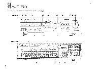
REAR PANEL PARTS AND THEIR FUNCTiONS. jai 1,ic041W'0. AVC-50 ,4491*, (1) REMCTE CONTROL Cable Connectors Use these to connect compatible Yamaha components (with an H40 mark) to your amplifier for remote control of each component. The cables for each component are supplied with the AC-50. PHONO-Connect to a turntable using the cable with a mini-olug :;onnector. TUNER-Connect to a tuner using the cable with a 5-pin conne:;tor. TAPE-Connect to a cassette tape deck using the cable with a 6-pin connector. ® Video Signal Connection Terminals Use these to connect the video signal cables from your components to the amplifier. They should be connected to the proper input/output jacks for each unit. TV-Connect a TV tuner here. VDP-Connect a video disc player here. VCR 1-Connect a video recorder here for both recording arid playback. VCR 2-Connect a second video recorder here for both recording and playback. MONITOR OUT 1-Connect this to the video IN terminal on a video monitor. MONITOR OUT 2-Connect this to the video IN terminal on a second video monitor. ® Audio Signal Connection Terminals Use these to connect the audio signal cables from your components to the amplifier. They should be connected to the proper input/output jacks for each unit. Be sure that L and R channels are connected consistently. PHONO-Connect a turntable here. GND---Connect the ground wire from a turntable here. CD-Connect a compact disc player here. TUNER-Connect a tuner here. AUX-Connect another audio component here A turntable cannot be connected to these terminals. TAPE 1-Connect a cassette tape deck. TAPE 2-Connect a second audio tape deck here. TV-Connect a TV tuner here. VDP-Connect a video disc player here. VCR 1-Connect a video cassette recorder here for both recording and playback. VCR 2-Connect a second video cassette recorder here for both recording and playback. (4) OUTPUT Terminals These terminals allow a number of system connection possibilities The bars connecting the REAR and MAIN IN terminals may be left as is, removed, or changed according to the system connection configuration you select. See the Connections section for a detailed explanation of how these terminals are used for each system configuration. (t) BALANCE Control Use this rotary control to concurrently change the left and right output volume to the speaker terminals, from full left (L), to balanced right and left (0), to full right (R). ® SPEAKER Connection Terminals A pair of speakers can be connected here. See the Connections portion of this manual for details on speaker connections. AC Power Cord Use this to connect the amplifier to an AC wall outlet. *AC OUTLETS Use these to connect the power cords from your components to the amplifier. The power to the three switched outlets is controlled by the amplifier's power switch. They will supply power to any component that is connected to them whenever the AVC-50 is turned on, whether by the front panel-power switch or by the remote control power switch. The power to the two unswitched outlets is not controlled by the amplifier. They will continually supply power to any unit connected to them, therefore, units with clocks, such as VCRs, should be connected here. Note that the AC outlets are size-coded for polarity, so insert plugs correctly. 7
-
 1
1 -
 2
2 -
 3
3 -
 4
4 -
 5
5 -
 6
6 -
 7
7 -
 8
8 -
 9
9 -
 10
10 -
 11
11 -
 12
12 -
13
-
14
-
15
-
16
-
17
-
18
-
19
-
20
-
21
-
22
-
23
-
24
-
25
-
26
 |
 |
