Yamaha AVC-50 AVC-50 OWNERS MANUAL - Page 6
AVC-50
 |
View all Yamaha AVC-50 manuals
Add to My Manuals
Save this manual to your list of manuals |
Page 6 highlights
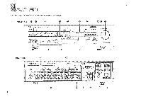
AVC-50 FRONT PANEL PARTS AND THE FUNCTIONS • POWER Switch This "oush-on, push-or" switch is used to supply power to your amplifier. Power Indicator This indicary gl a ,,Then power is supplied to the amplifier. • VIDEO ENHANCER Controls ON/OFF Switch-This switch is used to turn the Video Enhancer on and off. When this switch is pressed in, the Video Enhancer circuits are activated. PB/REC (Playback/Recording) Switch-This switch is used to select which signal is going to be video enhanced. When this switch is pressed in, the signal being recorded is video enhanced. When it is out, the signal being monitored is video enhanced. DETAIL Control-This rotary control is used to compensate for detail loss (i.e. increase subtle textures and eliminate smeaing). SHARPNESS Control-This rotary control is used to increase the sharpness of the picture (i.e. sharpen edges and contours). VIDEO LEVEL Control-This rotary control is used to increase the overall level of the enhanced video signal. 0 REAR LEVEL Volume Control Wher using the AVC-50 as a rear speaker amplifier, this control raises or lowers the volume to only the speakers connected to the rear panel speaker terminals. • Video Input Source Indicators These indicators light to show which video input source is selected. Audio Input Source Indicators These indicators light to show which audio input source is selected. CO PICTURE SELECTOR This seesaw type button is used to select the video source you wish to monitor (Video Cassette Recorder 2, Video Cassette Recorder 1, Video Disc Player, or Television Tuner). INPUT SELECTOR This seesaw type button is used to select the audio source you wish to monitor (Video Cassette Recorder 2, Video Cassette Recorder 1, Video Disc Player, Television Tuner, Tape Deck 2, Tape Deck 1, Auxiliary, Tuner, Compact Disc Player, or Turntable). O Audio Muting Indicator This indicator lights when Muting is engaged (from remote control unit). • VOLUME Control This rotary control is used to raise or lower the output volume level. It acts as a master volume control, increasing or decreasing the signal level to both front and rear speaker pairs. VCR 2 INPUT Jacks These jacks are used to connect a third video input source, such as a camera, to the amplifier. When connections are made here, any component connected to the rear panel VCR 2 input terminals is defeated. 410 PROCESSING MODE Controls INPUT BALANCE-This rotary control is used to concurrently change the Left and Right input volumes from full left (L), to balanced Right and Left (0), to full Right (R). DELAY TIME-This rotary control is used to vary the audio signal delay time, from 10 to 30 milliseconds, to the rear speaker pair. Processing Mode-This rotary switch is used to select one of 5 signal processing modes. These modes are effective only when the AVC-50 is driving a rear speaker pair in a 4-speaker system. OREC OUT PICTURE Selectors These buttons are used to select the video source to be sent to the Video REC OUT terminals, enabling video recording of any source, even while monitoring another • REC OUT SOUND Selectors These buttons are used to select the audio source to be sent to the audio REC OUT terminals, enabling audio recording of any source, even while monitoring another • BASS EXTENSION Switch This switch is used to activate a Yamaha circuit which effectively extends the low frequency output of the amplifier. • HIGH FILTER Switch This switch is used to activate a Yamaha circuit which effectively eliminates high-frequency noise from the audio signal. It is most effective with video sources. lJ REMOTE CONTROL Sensor This s useo !C) receive signals from the remote control unit. 6
-
 1
1 -
 2
2 -
 3
3 -
 4
4 -
 5
5 -
 6
6 -
 7
7 -
 8
8 -
 9
9 -
 10
10 -
 11
11 -
 12
12 -
13
-
14
-
15
-
16
-
17
-
18
-
19
-
20
-
21
-
22
-
23
-
24
-
25
-
26
 |
 |
