Yamaha AVC-50 AVC-50 OWNERS MANUAL - Page 10
FAITir,T]
 |
View all Yamaha AVC-50 manuals
Add to My Manuals
Save this manual to your list of manuals |
Page 10 highlights
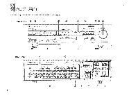
1,' l''''AAVC-50 System Connection Diagram Video Disc Player 7 VCR 1 VCR 2 TV with video input terminal Monitor 2 9 Video output term nal Audio outpt.t. terminal TV tuner Video output terminal Audio output terminal Remote terminal for turntable with: ,,!T• j mat = ANA vac.° Turntable FAITir,T] OUTPUT CD player with • CD Player mark Il Tuner . OUTPUT i . Remote terminal for tuner with #.Sti3O mark Remote terminal for swi-.j...9 tape deck with,SAMmark LINE OUT o •.•O Tapir Deck 1 LINE IN Video input terminal ,,, Audio input lerrninni-N r Video output terminal Video o-u-tput termin..a.,l.' "s Video input terminal Video input terminal 4O..ms weep emug C • C. I E TT E- LT- 1 Pm pp VI 21 Snap of &M. !'.>rts' f", ▪ 401. IRWIN ▪ •11111104M ti • 0 ufl• .06 Stereo Mono Cable Stereo Plug no Plug Tr • ; 60,trz:,;, Auoio Amp Input term nal for other than PHONO j Power plugs for other equipment (Unswitched) Handles up to 200 W Not linked to AVC-50 power switch Use this outlet for equipment with a clock. Power plugs for other equipment (Switched) Handles up to 300 W Linked to AVC-50 power switch Power cord polarity marks The power cord and AC outlet have polarity CUM indicators-a minus sign with the cord and sockets of a different size with the AC outlet. The purpose of this is to match polarities. Observe the polarity marks when connecting the AC outlets of amps and other equipment. a 0 • • • •••o Tape Deck 2 • Super Woofer (With Amplifier) Speakers • • Speakers 10
-
 1
1 -
2
-
3
-
4
-
 5
5 -
 6
6 -
 7
7 -
 8
8 -
 9
9 -
 10
10 -
 11
11 -
 12
12 -
 13
13 -
 14
14 -
 15
15 -
16
-
17
-
18
-
19
-
20
-
21
-
22
-
23
-
24
-
25
-
26
 |
 |
