Yamaha DSP-A970 Owner's Manual
Yamaha DSP-A970 Manual
 |
View all Yamaha DSP-A970 manuals
Add to My Manuals
Save this manual to your list of manuals |
Yamaha DSP-A970 manual content summary:
- Yamaha DSP-A970 | Owner's Manual - Page 1
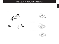
DSP-A970 DIGITAL SOUND FIELD PROCESSING AMPLIFIER OPERATION MANUAL CONTENTS SAFETY INSTRUCTIONS Inside Front Cover SETUP & ADJUSTMENT 3 1-1.GETTING STARTED 3 1-2.SETUP 10 1-3.CONTROLS & ADJUSTMENTS 18 1-4.ADJUSTMENT 22 GENERAL OPERATION 27 2-1.PLAYING A SOURCE 27 2-2.RECORDING A SOURCE TO - Yamaha DSP-A970 | Owner's Manual - Page 2
The unit has been dropped, or the cabinet damaged. 16 Servicing - The user should not attempt to service the unit beyond those means described in the operating instructions. All other servicing should be referred to qualified service personnel. 17 Power Lines - An outdoor antenna should be located - Yamaha DSP-A970 | Owner's Manual - Page 3
For A Lifetime YAMAHA and the Electronic Industries control to "-∞" while lowering the tonearm to play a record; turn the volume up with the stylus in the groove. 8 Be sure to read the "Troubleshooting instructions found in the users manual please try to eliminate the problem by using one of the - Yamaha DSP-A970 | Owner's Manual - Page 4
DSP system takes full advantage of Yamaha's undisputed leadership in the field of digital audio processing to bring you a whole new world of listening experiences. Follow the instructions in this manual of amplification on the DSP-A970 mean that no additional amplifiers are required to enjoy - Yamaha DSP-A970 | Owner's Manual - Page 5
operations, you should begin by installing the supplied batteries. 1. Turn the remote control unit over and slide the battery compartment cover downward in the direction of the arrow. Remote control Batteries User program sheets 2. Insert the batteries (R6, AA, UM-3 type), being careful to - Yamaha DSP-A970 | Owner's Manual - Page 6
USER/LEARN switch on the remote control unit is set to the YPC or USER position for normal operation. q This remote control uses an advanced, highly directional infrared beam. Be sure to aim the remote control directly at the remote control has made it possible for Yamaha engineers to bring you this - Yamaha DSP-A970 | Owner's Manual - Page 7
in automatic input balance control. This always assures you the best performance without manual adjustment. Manufactured under YAMAHA "CINEMA DSP" logo indicates these programs created by the combination of Dolby Pro Logic and YAMAHA DSP technology. Directional Enhancement Circuit + DSP The YAMAHA - Yamaha DSP-A970 | Owner's Manual - Page 8
it. Best results, however, are obtained with the full system. It is also possible to further expand your system with the addition of a subwoofer and amplifier.You may wish to choose the convenience of a Yamaha Active Servo Processing Subwoofer System, which has its own built-in power - Yamaha DSP-A970 | Owner's Manual - Page 9
English Four Possible Types of Speaker System Configurations Recommended 4 Speaker System 5 Speaker System 6 Speaker System 7 Speaker System Simplest system. Good for Audio/Video sources and Dolby Pro Logic Surround. You can enjoy widely diffused sound by only adding two additional speaker - Yamaha DSP-A970 | Owner's Manual - Page 10
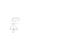
power handling capacity to accept the maximum output of the DSP system or the external amps that will drive them. Place the MAIN SPEAKERS in the use a magnetically shielded speaker.) If using a SUBWOOFER, such as a Yamaha Active Servo Subwoofer System, the position of the speaker is not so critical - Yamaha DSP-A970 | Owner's Manual - Page 11
English VIDEO SUPERIMPOSE If you connect your video cassette recorder, video disc player, video monitor, etc. to this unit, you can take advantage of this unit's capability to display program titles, parameter data and information about other various settings and adjustments on your video monitor's - Yamaha DSP-A970 | Owner's Manual - Page 12
1-2. SETUP Before you start making connections make sure all related electronic components are turned OFF. REAR PANEL (General Model) 10 CAUTION: TO PREVENT ELECTRIC SHOCK, DO NOT USE THIS (POLARIZED) PLUG WITH AN EXTENSION CORD, RECEPTACLE OR OTHER OUTLET UNLESS THE BLADES CAN BE FULLY INSERTED - Yamaha DSP-A970 | Owner's Manual - Page 13
using two center speakers, or to "A or B" when using only one center speaker. 9 Rear Effect Speaker Terminals When using the built-in rear-channel amplifier, connect the rear effect speakers here. 0 GND Terminal Connects the ground wire of the turntable to produce minimum hum. In some cases, however - Yamaha DSP-A970 | Owner's Manual - Page 14
amplifier will be turned off and no output will be available at the speaker terminals. Rear Panel Switch and Control Settings There are several switches and controls which your video equipments employ. (General Model only) General Instructions for Connections Make sure that you have the left (L) and - Yamaha DSP-A970 | Owner's Manual - Page 15
CONNECTING AUDIO/VIDEO SOURCE EQUIPMENTS TO THIS UNIT CD player Tuner Tape deck 1 Tape deck 2 Turntable Monitor TV Video disc player TV/Satellite tuner Video cassette recorder 1 Video cassette recorder 2 13 English - Yamaha DSP-A970 | Owner's Manual - Page 16
CONNECTING TO S VIDEO JACKS If your video cassette recorder, video disc player, etc. and your monitor are equipped with "S" (high-resolution) video terminals, connect them to this unit's S VIDEO jacks, and connect this unit's S VIDEO MONITOR OUT jack to the "S" video input of your monitor. Otherwise - Yamaha DSP-A970 | Owner's Manual - Page 17
English CONNECTING THE MAIN SPEAKERS AND CENTER SPEAKER(S) TO THIS UNIT Connect the MAIN speakers to the MAIN speaker output terminals of this unit. Connect the CENTER speaker to the CENTER speaker output terminals. If you will be using one CENTER speaker, connect it to either the A or B terminals - Yamaha DSP-A970 | Owner's Manual - Page 18
and connect the corresponding speaker pair to the speaker terminals of the external amp. NOTE: If the pin plug is inserted in the FRONT/REAR EFFECT out jacks, the speaker output from the built-in amplifier will be cut off. Front effect speaker This unit Front effect speaker Rear effect speaker - Yamaha DSP-A970 | Owner's Manual - Page 19
the LOW PASS jack to the INPUT jack of the subwoofer amplifier, and connect the speaker terminals of the subwoofer amplifier to the subwoofer. With some subwoofers, including the Yamaha Active Servo Processing Subwoofer System, the amplifier and subwoofer are in the same unit. CONNECTING SPEAKER - Yamaha DSP-A970 | Owner's Manual - Page 20
unit switches the unit to the STANDBY mode. (In this mode, the indicator is half illuminated.) 2 Remote control sensor Signals from the remote control unit are received here. 3 Pro Logic Decoder Indicator Illuminates while the built-in Dolby Pro Logic Surround Decoder is being activated. 4 Sound - Yamaha DSP-A970 | Owner's Manual - Page 21
adjustments. 7 Effect Switch Normally ON, this switch can be turned OFF to disable output from the center and effect speakers. 8 Master Volume Control Simultaneously controls signal level at all outputs: front effect, main, rear effect, center, and subwoofer. (This does not affect TAPE REC OUT level - Yamaha DSP-A970 | Owner's Manual - Page 22
User mode, blinks when a learned key is pressed to show that a control signal has been sent to your equipment. 2 YPC/USER/LEARN Switch Set to YPC for operating this unit and Yamaha equipments. Set to USER set to 2, they operate the LD player. 6 Test Switch When pressed, sends a signal to the main - Yamaha DSP-A970 | Owner's Manual - Page 23
Select DSP programs 1 through 12. K Tuner Function Keys Operate Yamaha tuner functions. L Tape Deck Function Keys Operate Yamaha tape deck functions. M Blank Keys Have no preset functions, so are used for learning other remote controller's functions only. N 1/2 Switch When the YPC/USER/LEARN Switch - Yamaha DSP-A970 | Owner's Manual - Page 24
center and rear level again. Volume controls on external power amplifiers may also be adjusted if necessary to achieve proper balance. 3. For the front effect speaker level adjustment, depress the TEST switch on the remote control again so that "TEST DSP" appears in the display panel. A calibration - Yamaha DSP-A970 | Owner's Manual - Page 25
to a convenient listening level (you will use this as your "reference" level). Front panel Remote control or * This adjustment can also be done with the remote control unit. For using the remote control unit, refer to "5. Input level adjustment (INPUT LVL TRIM)" on page 26. 6. In the same - Yamaha DSP-A970 | Owner's Manual - Page 26
video image). So, to use this function, first turn the monitor on. 1. Set the PARAMETER/SET MENU switch to the SET/MENU position on the remote control unit. 2. Select an item (title) of setting/adjustment. 3. Select any desired mode or edit parameters on the item. In the same way, perform settings - Yamaha DSP-A970 | Owner's Manual - Page 27
done to each frequency individually. Operating procedure After selecting the item (title) in step 2 on the previous page, press the Parameter + or - key on the remote control to display the condition of the equalizer. Then select a frequency with the Parameter Select keys on the - Yamaha DSP-A970 | Owner's Manual - Page 28
The following functions on this unit can be locked by this operation. • DSP parameters • Other setting/adjustment items in the "SET/MENU" mode (CENTER TRIM) • ON SCREEN display key • INPUT TRIM control • FRONT, REAR and CENTER level +/- keys • TEST switch 5. Input level adjustment (INPUT LVL TRIM) - Yamaha DSP-A970 | Owner's Manual - Page 29
etc., or select a desired sound field program. (See page 29.) NOTE: If a different audio source is selected with the input selector keys on the remote control unit while enjoying a video source, the sound from the newly selected audio source is heard, but the picture from the video source can still - Yamaha DSP-A970 | Owner's Manual - Page 30
operation. 4. Select an input source to be played (and to be recorded). (See page 27 for the method of input source selection.) Front panel Remote control 2. Within 5 seconds after the REC OUT switch is pressed, select the "SOURCE" position with the input selector switch (so that "REC OUT SOURCE - Yamaha DSP-A970 | Owner's Manual - Page 31
deck or VCR. 6. While recording a source, you can enjoy listening to and/or watching another source selected with an input selector switch. Front panel Remote control or While recording, you can monitor the audio and/or video signals to be recorded by selecting the tape deck or VCR used for - Yamaha DSP-A970 | Owner's Manual - Page 32
various parameters that can be adjusted to the listener's taste. 2-4. SELECTING SOUND FIELD PROGRAMS 1. Set the PARAMETER/SET MENU switch on the remote control to the PARAMETER position. PARAMETER SET MENU 2. Select the desired sound field program by pressing the PROGRAM selector on the front panel - Yamaha DSP-A970 | Owner's Manual - Page 33
no display, press the key twice. 2-5. MUTING THE EFFECT SOUND The EFFECT switch on the front panel and the EFFECT ON/OFF key on the remote control unit make it simple to compare the normal stereo sound with the fully processed effect sound. To mute the effect sound and monitor only the - Yamaha DSP-A970 | Owner's Manual - Page 34
2-7. DESCRIPTIONS OF THE SOUND FIELD PROGRAMS The following list gives brief descriptions of the sound fields produced by each of the DSP programs. Keep in mind that most of these are precise digital recreations of actual acoustic environments. The data for them was recorded at the locations - Yamaha DSP-A970 | Owner's Manual - Page 35
English 3. CONCERT HALL 3 Hall E in Europe: A classic large shoe-box type concert hall with approximately 2200 seats. It has a circular stage and seats located behind the stage. 5. ROCK CONCERT The Roxy Theatre: The ideal program for lively, dynamic rock music. The data for this program was - Yamaha DSP-A970 | Owner's Manual - Page 36
7. TV THEATER 1 Game/Amusement: The sound field of a disco is used for the front presence side, and the sound field of a concert hall in Vienna is used for the rear surround side. This program reproduces video game music etc. more vividly emphasizing the fast tempo and lightness of the music. If - Yamaha DSP-A970 | Owner's Manual - Page 37
English 9. CONCERT VIDEO Classical/Opera: This program provides excellent depth of vocals and overall clarity, restraining excessive reverberation. For opera, the orchestra pit and the stage are ideally combined, letting you feel a full presence sound. The rear surround side of the sound field is - Yamaha DSP-A970 | Owner's Manual - Page 38
soundtracks) encoded with the Dolby Surround system. NOTE: If the main and center channel sound is considerably altered by overadjustment of the BASS or TREBLE controls, the relationship with the rear channels may produce an unnatural effect. - Yamaha DSP-A970 | Owner's Manual - Page 39
the main unit and other connected Yamaha audio and video equipment, has a sophisticated "learning" function that allows it to control other equipment in your system equipped with infrared remote control receivers. By setting the YPC/USER/LEARN switch on the remote control unit to "LEARN", all keys - Yamaha DSP-A970 | Owner's Manual - Page 40
flashes on and off three times. Erasing All Learned Functions 1. Set the YPC/USER/LEARN switch to "LEARN". 2. Use the point of a pencil or other employed by the other remote control unit, that this unit will not be able to learn its signals. NOTE: When the remote control freezes, press the RESET - Yamaha DSP-A970 | Owner's Manual - Page 41
hall, a dance floor, or virtually any size room at all. This ability to create sound fields at will is exactly what Yamaha has done with the DSP system. DSP programs consist of some parameters to determine apparent room size, reverberation time, distance from you to the performer, etc. In each - Yamaha DSP-A970 | Owner's Manual - Page 42
direct sound. The "ROOM SIZE" parameter provided in many of the DSP programs alters the timing between these reflections, thus changing the shape of the sound, and its control range. 1. With the desired program selected, press the Parameter Select (w) key on the remote control unit once. This will - Yamaha DSP-A970 | Owner's Manual - Page 43
within the acoustic environment. What it Does: Adjusts the delay between the direct sound and the first reflection heard by the listener. Control Range: 1 - 49 milliseconds Changing this parameter from 1 to 2 increases the apparent volume of the room eight times (length, width, and height all - Yamaha DSP-A970 | Owner's Manual - Page 44
the early reflection decay rate, and thus the "liveness" of the room. What it Does: Changes the rate at which the early reflections decay. Control Range: 0 - 10. q REV. TIME (Reverberation Time) How it Affects the Sound: The natural reverberation time of a room depends primarily on its size and the - Yamaha DSP-A970 | Owner's Manual - Page 45
q DOLBY PRO LOGIC (for MOVIE THEATER only) By adding the Dolby Pro Logic Decoder to the DSP effect, the full presence of a 70 mm film theater is reproduced without deteriorating the channel separation. the value, the later the effect sounds are generated. Control Range: 15 - 30 milliseconds 43 - Yamaha DSP-A970 | Owner's Manual - Page 46
TROUBLESHOOTING PROBLEM Power does not come on. Hum. No sound. No sound from the effect speakers. No sound from the front effect speakers. No sound from the center speaker. The sound suddenly goes off. DSP of flourescent lamp etc.) is striking the remote control sensor of the main unit. This unit - Yamaha DSP-A970 | Owner's Manual - Page 47
01% CD/TUNER/TAPE/LD/VCR/TV·DBS/AUX to SP OUT 35W/8Ω, MAIN L/R, 20 Hz - 20 kHz 0.02% 10W/8Ω, FRONT L/R, REAR L/R, 1 kHz 0.3% Built-in amplifier 35W/8Ω, MAIN L/R, CENTER, 20 Hz - 20 kHz 0.008% 10W/8Ω, FRONT L/R, REAR L/R, 20 Hz - 20 kHz 0.03% Signal-to-Noise Ratio (IHF-A Network) PHONO MM (Input - Yamaha DSP-A970 | Owner's Manual - Page 48
Tone Control Characteristics Bass Boost/Cut 10 dB (50 Hz) Turnover frequency 350 Hz CROISSY-BEAUBOURG 77312 MARNE-LA-VALLEE CEDEX02, FRANCE YAMAHA ELECTRONICS (UK) LTD. YAMAHA HOUSE, 200 RICKMANSWORTH ROAD WATFORD, HERTS WD1 7JS, ENGLAND YAMAHA SCANDINAVIA A.B. J A WETTERGRENS GATA 1, BOX 30053
-
 1
1 -
 2
2 -
 3
3 -
 4
4 -
 5
5 -
 6
6 -
 7
7 -
8
-
9
-
10
-
11
-
12
-
13
-
14
-
15
-
16
-
17
-
18
-
19
-
20
-
21
-
22
-
23
-
24
-
25
-
26
-
27
-
28
-
29
-
30
-
31
-
32
-
33
-
34
-
35
-
36
-
37
-
38
-
39
-
40
-
41
-
42
-
43
-
44
-
45
-
46
-
47
-
48
 |
 |
DSP-A970
DSP-A970
CONTENTS
SAFETY INSTRUCTIONS
.............................
Inside Front Cover
SETUP & ADJUSTMENT
..........................................................
3
1-1.GETTING STARTED
...........................................................
3
1-2.SETUP
................................................................................
10
1-3.CONTROLS & ADJUSTMENTS
.......................................
18
1-4.ADJUSTMENT
...................................................................
22
GENERAL OPERATION
.........................................................
27
2-1.PLAYING A SOURCE
........................................................
27
2-2.RECORDING A SOURCE TO AUDIO/VIDEO TAPE
(OR DUBBING FROM A TAPE TO ANOTHER)
...............
28
2-3.DIGITAL SOUND FIELD PROGRAMS
.............................
30
2-4.SELECTING SOUND FIELD PROGRAMS
......................
30
2-5.MUTING THE EFFECT SOUND
.......................................
31
2-6.SUPERIMPOSED VIDEO PROGRAM/PARAMETER
DISPLAY
............................................................................
31
2-7.
DESCRIPTIONS OF THE SOUND FIELD PROGRAMS
....
32
2-8.REMOTE CONTROL “LEARNING” FUNCTION
..............
37
CREATING YOUR OWN SOUND FIELDS
............................
39
3-1.
SELECTING AND EDITING PROGRAM PARAMETERS
....
39
3-2.
DESCRIPTIONS OF THE DIGITAL SOUND FIELD
PARAMETERS
....................................................................
41
TROUBLESHOOTING
.............................................................
44
SPECIFICATIONS
...................................................................
45
DIGITAL SOUND FIELD
PROCESSING AMPLIFIER
OPERATION MANUAL