Yamaha EMX312SC Owner's Manual - Page 20
Reference, Controls and Connectors, Controls on Each Channel - setup
 |
UPC - 086792831336
View all Yamaha EMX312SC manuals
Add to My Manuals
Save this manual to your list of manuals |
Page 20 highlights
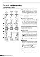
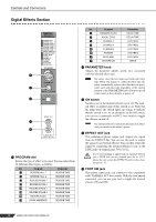
Controls and Connectors Controls and Connectors Controls on Each Channel Channels 1 to 4 (Monaural) Channels 5/6 and 7/8 (Stereo) Channels 9/10 and 11/12 (Stereo) 1 1 1 2 3 3 3 4 4 4 5 5 5 6 7 9 8 1 FCL (Feedback Channel Locating) lamp This lamp is used during setup to identify any channel that might be howling. Check these lamps when setting up for a performance. If the lamp lights up, adjust the channels equalizer 2 or level knob 5 to reduce the level so that the lamp goes off. NOTE Input of a continuous sound (as from a CD player or vocal) may cause the lamp to come on even in the absence of howling. 2 Equalizer (HIGH, MID, and LOW) This three-band equalizer adjusts the channel's high, mid, and low frequency bands. Setting the knob to the position produces a flat frequency response. Turning the knob to the right boosts the corresponding frequency band, while turning to the left attenuates the band. The following table shows the equalization type, the base frequency, and the maximum cut/boost for each of the three bands. Band HIGH MID LOW Type Shelving Peaking Shelving Base Frequency 10 kHz 2.5 kHz 100 Hz Maximum Cut/Boost ±15 dB 3 MONITOR control Adjusts the level of the signal sent from the channel into the MONITOR bus. If input is from a stereo channel pair (5/6, 7/8, 9/10, or 11/12), the signals from the L and R channels are mixed before moving into the bus. The MONITOR bus signal is output at the MONITOR OUT jack O, and may also be output from the SPEAKERS A jacks V (depending on the setting of the POWER AMP switch R). NOTE The channel's LEVEL knob 5 has no effect on the level of the signal sent into the MONITOR bus. 4 EFFECT knob Adjusts the level of the signal sent from the channel into the EFFECT bus. If input is from a stereo channel pair (5/6, 7/8, 9/10, or 11/12), the signals from the L and R channels are mixed before moving into the bus. The EFFECT bus signal is fed both to the internal digital effector and to the EFFECT OUT jack C. NOTE The channel's LEVEL knob 5 also affects the level of the channel's signal into the EFFECT bus. 5 LEVEL knob Adjusts the signal's output level. Use these knobs to adjust the volume balance among the various channels. NOTE To reduce noise, set the knobs for unused channels to "0". 20 EMX512SC/EMX312SC/EMX212S
-
 1
1 -
2
-
3
-
4
-
5
-
6
-
7
-
8
-
9
-
10
-
11
-
12
-
13
-
14
-
 15
15 -
 16
16 -
 17
17 -
 18
18 -
 19
19 -
 20
20 -
 21
21 -
 22
22 -
 23
23 -
 24
24 -
 25
25 -
26
-
27
-
28
-
29
-
30
-
31
-
32
-
33
-
34
-
35
-
36
 |
 |
