Yamaha EMX312SC Owner's Manual - Page 23
MAIN Graphic Equalizer, EFFECT RETURN knob, MASTER knob, LEVEL meters, MAIN OUT L and R jacks
 |
UPC - 086792831336
View all Yamaha EMX312SC manuals
Add to My Manuals
Save this manual to your list of manuals |
Page 23 highlights
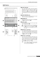
MAIN Section E F J Controls and Connectors E Graphic Equalizer This 7-band graphic equalizer adjusts the frequency characteristics of the stereo signal on the MAIN L and MAIN R buses. This is the signal that is output to the MAIN OUT jacks I and to the SPEAKERS jacks V. Each band can be adjusted by ±12 dB. The base frequencies for the bands are: 125, 250, 500, 1k, 2k, 4k and 8k Hz. F EFFECT RETURN knob Adjusts the level of the signal sent from the internal effector to the MAIN L and MAIN R buses. G MASTER knob Adjusts the level of the signal output to the SPEAKERS H jacks V and MAIN OUT jacks I. H LEVEL meters The L and R meters show the level of the signal output from the MAIN OUT jack I. G The MAIN OUT signal also passes through the inter- nal power amp and is then output at the SPEAKERS jacks V. Keep an eye on the LIMITER lamps Q to ensure that the level at the SPEAKERS jacks does not stay too high. I MAIN OUT L and R jacks These unbalanced phone output jacks feed out the main I stereo output. You would typically connect these jacks to a power amp or powered speakers. The signal sent to these jacks is adjusted by the MAIN section's MASTER knob G and graphic equalizer E. J REC OUT L and R jacks These RCA pin-type unbalanced output jacks can be used to send the main stereo signal to an external DAT recorder or cassette recorder. Note that unlike the output from the MAIN OUT jacks, the signal from the REC OUT jacks is not adjusted by the MAIN section's MASTER knob G and graphic equalizer E. NOTE Since this output signal is not adjusted by the MAIN section's MASTER knob G, you should adjust the level as necessary at the recording side. EMX512SC/EMX312SC/EMX212S 23
-
 1
1 -
2
-
3
-
4
-
5
-
6
-
7
-
8
-
9
-
10
-
11
-
12
-
13
-
14
-
15
-
16
-
17
-
 18
18 -
 19
19 -
 20
20 -
 21
21 -
 22
22 -
 23
23 -
 24
24 -
 25
25 -
 26
26 -
 27
27 -
 28
28 -
29
-
30
-
31
-
32
-
33
-
34
-
35
-
36
 |
 |
