Yamaha PSR-340 Owner's Manual - Page 7
• Rear Panel, MAIN A/B AUTO FILL buttons - specifications
 |
View all Yamaha PSR-340 manuals
Add to My Manuals
Save this manual to your list of manuals |
Page 7 highlights
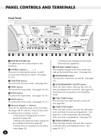
PANEL CONTROLS AND TERMINALS ƹ MAIN A/B (AUTO FILL) buttons When the Style mode is selected, these are used to change auto accompaniment sections and control the Auto Fill function. (See page 54.) ƺ CHORD GUIDE button When the Style mode is selected, this is used to control the Chord Guide functions. (See page 62.) ƻ RECORD button This is used for selecting and enabling the recording functions: Song (pages 80, 84), EZ Chord (page 68), and One Touch Setting (page 72). Ƽ ONE TOUCH SETTING / SONG MEMORY buttons When the Style mode is selected, these are used to select the One Touch Setting registrations (page 73). When the Song mode is selected, these are used to select specific tracks (pages 81, 85). ƽ HARMONY button This turns the Harmony effect on and off. (See page 43.) ƾ REVERB button This turns the Reverb effect on and off. (See page 40.) ƿ DUAL button This turns the Dual mode on and off. (See page 34.) TOUCH button This turns the Touch function on and off. (See page 38.) Power switch (STANDBY/ON) DEMO button This is used to play the Demo songs. (See page 12.) LOAD, SAVE, UTILITY buttons These are for using the corresponding disk operations. (See pages 96, 94, 97.) EXECUTE button This is for executing disk operations. (See page 95.) Disk Drive This is for insertion of floppy disks, for loading and saving data. (See page 92.) Rear Panel DC IN 10 12V IN MIDI OUT FOOT SWITCH PHONES/ OUTPUT DC IN 10 12V ¿ » · AC POWER ADAPTOR ³ YAMAHA PA-5B/5C/51 AC POWER ADAPTOR YAMAHA PA-5B/5C/51 ³ DC IN 10-12V jack This is for connection to a PA-5B, PA-5C or PA-51 AC power adaptor. (See page 8.) · PHONES/OUTPUT jack This is for connection to a set of stereo headphones or to an external amplifier/speaker system. (See page 9.) » FOOT SWITCH jack This is for connection to an optional FC4 or FC5 Footswitch. The footswitch is generally used to control sustain, but it can conveniently be set to control one of a variety of functions instead. (See pages 9, 100.) ¿ MIDI IN, OUT terminals These are for connection to other MIDI instruments and devices. (See page 103.) 7 5
-
 1
1 -
 2
2 -
 3
3 -
 4
4 -
 5
5 -
 6
6 -
 7
7 -
 8
8 -
 9
9 -
 10
10 -
 11
11 -
 12
12 -
13
-
14
-
15
-
16
-
17
-
18
-
19
-
20
-
21
-
22
-
23
-
24
-
25
-
26
-
27
-
28
-
29
-
30
-
31
-
32
-
33
-
34
-
35
-
36
-
37
-
38
-
39
-
40
-
41
-
42
-
43
-
44
-
45
-
46
-
47
-
48
-
49
-
50
-
51
-
52
-
53
-
54
-
55
-
56
-
57
-
58
-
59
-
60
-
61
-
62
-
63
-
64
-
65
-
66
-
67
-
68
-
69
-
70
-
71
-
72
-
73
-
74
-
75
-
76
-
77
-
78
-
79
-
80
-
81
-
82
-
83
-
84
-
85
-
86
-
87
-
88
-
89
-
90
-
91
-
92
-
93
-
94
-
95
-
96
-
97
-
98
-
99
-
100
-
101
-
102
-
103
-
104
-
105
-
106
-
107
-
108
-
109
-
110
-
111
-
112
-
113
-
114
-
115
-
116
-
117
-
118
-
119
-
120
-
121
-
122
-
123
-
124
-
125
-
126
-
127
-
128
 |
 |
